DRIVE SHAFT / PROPELLER SHAFT PROPELLER SHAFT ASSEMBLY DISASSEMBLY
PROCEDURE

 1.REMOVE PROPELLER SHAFT SPLINE SLEEVE
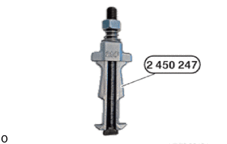
for Front Side:
Prepare special tool 2 450 247.
- SST
- 09300-WA190
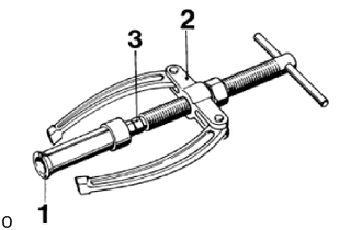
Prepare special tool 0 490 497 (00 8 550).
- SST
- 09300-WA200
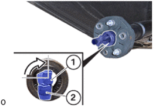
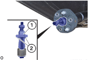
Insert pin (1) and the pin (2) of the special tool 2 450 247 in the propeller shaft spline sleeve of the propeller shaft assembly.
- SST
- 09300-WA190
Turn pin (1) by 90° in relation to pin (2).
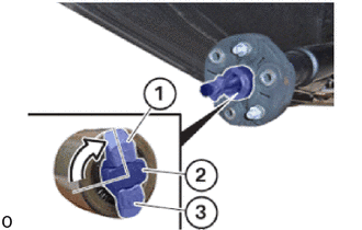
Insert the pin (2) between pins (1) and (3) of the special tool 2 450 247 in the propeller shaft spline sleeve of the propeller shaft assembly.
- SST
- 09300-WA190
Lock the special tool 2 450 247 by turning the sleeve (1).
- SST
- 09300-WA190
The pins (2) are retained by the sleeve (1).
Install the guide sleeve (1).
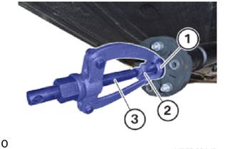
Bolt special tool 0 490 497 (00 8 550) to special tool 2 450 247 (2) and brace on the guide sleeve (1).
- SST
- 09300-WA200
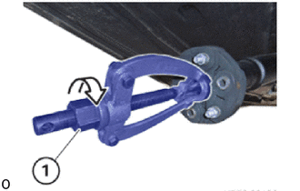
Turn nut (1) in direction of arrow and pull out the propeller shaft spline sleeve.
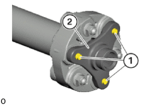
for B58 Rear Side:
Remove the E16 bolts.
Remove the three-hole frange (2)
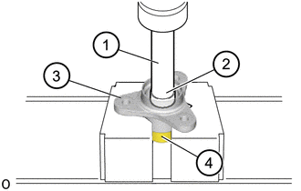
Press the propeller shaft spline sleeve (4) out of the three-hole flange (4) with the SST (1) and (2) in a press.
- SST
- 09950-70010 (09951-07100)
09950-60011 (09951-00250)
37334D
2.REMOVE REAR PROPELLER SHAFT BOOT
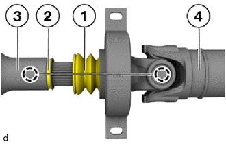
Pull off the rear propeller shaft boot (1) and the groove (2).
Mark the alignment of the installation positions of the front propeller shaft assembly (3) and the rear propeller shaft assembly (4).
- HINT:
-
The identification allows the front and rear propeller shaft assemblies to be installed at the same position. This guarantees that the propeller shaft assembly will once again be balanced within the system following installation.
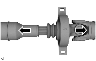
Pull apart the front and rear propeller shaft assemblies in the directions of the arrows.
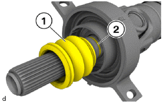
Release the rear propeller shaft boot (1) from the groove (2) using a screwdriver and pull it off over the longitudinal splines.
37230
3.REMOVE CENTER NO. 1 SUPPORT BEARING ASSEMBLY
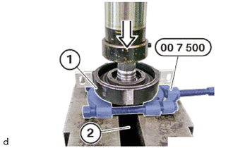
Install the special tool 0 490 482 (00 7 500) between the center No. 1 support bearing assembly (1) and the rear propeller shaft assembly (2).
- SST
- 09500-WA230
Use the hydraulic press to push the center No. 1 support (1) off the rear propeller shaft assembly (2).
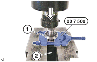
Use the hydraulic press to push the center No. 1 support bearing (1) off the rear propeller shaft assembly (2).