MIRROR (EXT) OUTER REAR VIEW MIRROR DISASSEMBLY
CAUTION / NOTICE / HINT
- NOTICE:
- ·
Scratches.
Tools and sharp-edged components can cause scratches.
-Protect working area.
-Handle tools and components carefully.
- HINT:
-
Description is for left component only. Procedure on the right side is identical.
PROCEDURE

 87961
1.REMOVE OUTER MIRROR
87945
2.REMOVE OUTER MIRROR COVER
87909
3.REMOVE OUTER MIRROR ACTUATOR ASSEMBLY
for Type A:
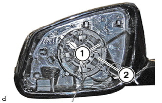
Release the 3 T10 screws (1) and pull out the outer mirror actuator assembly (2) a little.
for Type B:
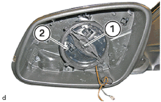
Release the T10 screws (1) and pull out the outer mirror actuator assembly (2).
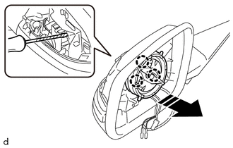

|
Separate in this Direction |
Using a screwdriver with its tip wrapped in protective tape, disengage the claw to separate the outer mirror actuator assembly as shown in the illustration.
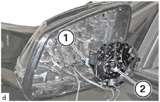
Remove the outer mirror actuator assembly (2).
8794A
4.REMOVE NO. 2 OUTER MIRROR COVER
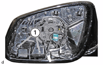
Loosen the T10 screws (1).
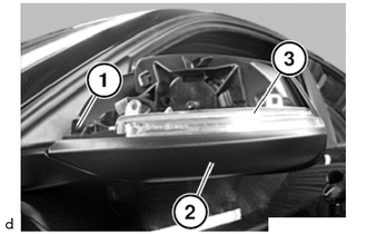
Loosen the T10 screw (1).
Feed out the No. 2 outer mirror cover (2) carefully.
Unlock and disconnect the connector to the side turn signal light assembly (3).
81740
5.REMOVE SIDE TURN SIGNAL LIGHT ASSEMBLY
87941A
6.REMOVE OUTER MIRROR VISOR
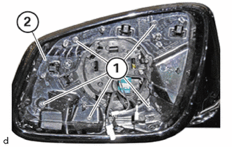
Loosen the T10 screws (1).
Slide the outer mirror visor (2) out.
87945C
7.REMOVE OUTER MIRROR LOWER COVER
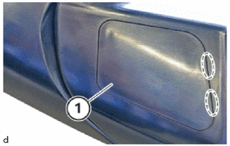
Detach the claws to remove the outer mirror lower cover (1).
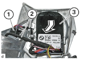
8.REMOVE OUTER MIRROR CONTROL ECU ASSEMBLY

|
Pull in this Direction |
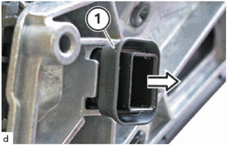
Pull out the connector housing (1) in the direction of the arrow.
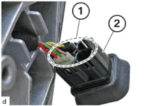
Unlock all connectors (1) on the connector housing (2) and disconnect.
|
|
Slide in this Direction |
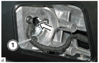
Slide out all cables (1) in the direction of the arrow.
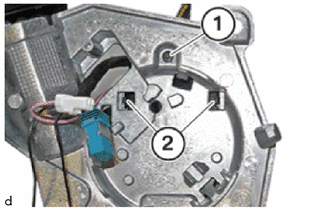
Loosen the T10 screw (1).
Detach the claws (2).
|
|
Remove in this Direction |
Unlock and disconnect the connector (1).
Detach the guides (2).
Remove the outer mirror control ECU assembly (3) in the direction of the arrow.