B48 INTAKE / EXHAUST TURBO CHARGER ACTUATOR AND LINK INSTALLATION
PROCEDURE

 17240
1.INSTALL TURBOCHARGER ACTUATOR AND LINK ASSEMBLY
- NOTICE:
- ·
Damage to the electrical controller drive and the mechanical connection.
Improper handling of the electrical controller drive can lead to malfunctions or failure of the electrical controller drive.
-Avoid exposure of lateral forces to the control rod of the electrical controller drive.
Replace turbocharger actuator and link assembly.
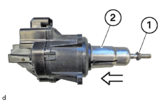
Insert and install the heat shield (2) in the direction of the arrow.
- HINT:
-
Component is contained in the repair kit.
Replace nut (1).
Insert and install the nut (1).
Screw on nut (1) to the limit position.
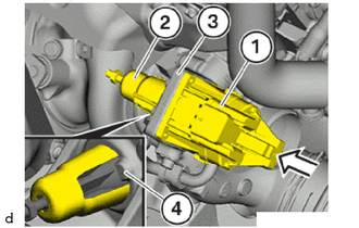
Feed turbocharger actuator and link assembly (1) with heat shield (2) into bore hole of compressor housing (3) in direction of arrow and position.
- HINT:
- ·
Make sure that the heat shield (2) is positioned correctly in relation to the groove (4) of the compressor housing (3).
·Component is contained in the repair kit.
Replace T25 bolts.
Tighten the T25 bolts.
- Torque:
- 3.0 N*m (31 kgf*cm, 27 in.*lbf)
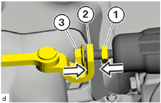
Slide the lever (2) of the wastegate valve carefully onto the control rod to the limit position.
- NOTICE:
-
Any effect of lateral force on the control rod must be avoided.
Position the nut (1) flush with the lever (2) of the wastegate valve.
- HINT:
-
Component is contained in the repair kit.
Replace nut (3).
Position the nut (3) flush with the lever (2) of the wastegate valve.
Connect connectors and lock.
- HINT:
-
The connector (1) must engage audibly.
17240
2.ADJUST TURBOCHARGER ACTUATOR AND LINK ASSEMBLY
Perform the following operations only when the setting for the electric wastegate valve controller is specified by the vehicle diagnosis.
Connect the diagnosis system:
- HINT:
-
-
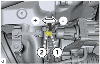
The adjusting nuts must be locked using two open-end spanners. If only one open-end spanner is used, there is a risk of the electrical controller drive being damaged.
Mark lock nut (2) and adjusting nut (1) with a colored mark.
Loosen lock nut (2).
According to the result of the diagnostic function: Shorten the adjustment travel (-) or lengthen the adjustment travel (+).
One rotation of adjusting nut = 0.75 mm adjustment travel
Example 1:
Measured actual value (via diagnostic function) = 0.75 mm
Required correction: +0.75 mm divided by 0.75 mm = +1.0 revolutions
- Torque:
- 6.6 N*m (67 kgf*cm, 58 in.*lbf)
- HINT:
-
For the correction of the setting of the control rod: Adjust the lock nut (1) in direction (+) by 1.0 revolutions and then readjust the adjusting nut (2).
Example 2:
Measured actual value (via diagnostic function) = -1.5 mm
Required correction: -1.5 mm divided by 0.75 mm = 2.0 revolutions
- Torque:
- 6.6 N*m (67 kgf*cm, 58 in.*lbf)
- HINT:
- ·
For the correction of the setting of the control rod: Adjust the adjusting nut (1) in direction (-) by 2.0 turns and then readjust the lock nut (2).
·After setting: Recheck the basic setting with the diagnostic function.
17880
3.INSTALL AIR CLEANER HOSE ASSEMBLY