B48 INTAKE / EXHAUST EXHAUST PIPE INSTALLATION
PROCEDURE

 1. EXHAUST PIPE ASSEMBLY
- CAUTION:
- ·
Component with heavy weight.
Danger of injury!
-Note component's center of gravity.
-Support component using a jack.
-Secure component against falling off the jack.
- ·
Heavy component.
Heavy components can lead to injury or damage.
-Remove and install heavy components with the aid of another person/other persons.
Insert and install the exhaust pipe assembly with the help of another person.
Replace nut.
Tighten the nut on the holder.
- Torque:
- 19 N*m (194 kgf*cm, 14 ft.*lbf)
Replace nuts.
Tighten the nuts on the holder.
- Torque:
- 19 N*m (194 kgf*cm, 14 ft.*lbf)
Replace nuts.
Tighten the nuts on the holder.
- Torque:
- 19 N*m (194 kgf*cm, 14 ft.*lbf)
for V-band Clamp:
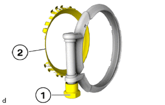
Unscrew the nut (1) and remove the sealing ring (2).
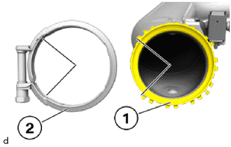
Mount the sealing ring (1) on the exhaust pipe assembly.
- NOTICE:
-
Make sure that the sealing ring (1) is correctly positioned for the V-clip (2).
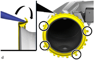
Bend all sheet metal tabs over with a suitable tool, except those in the marked areas.
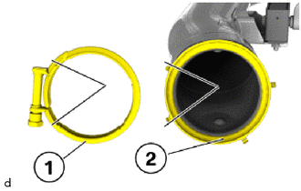
Mount the V-clip (1) on the sealing ring (2).
- NOTICE:
- ·
Make sure that the V-clip (1) is positioned correctly on the sealing ring (2).
·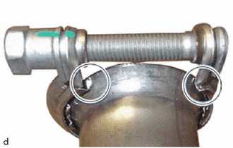
Make sure that the V-clip rests against the sheet metal tabs after mounting (marks).
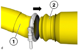
Connect the exhaust pipe assembly (1) with the catalytic converter (2) and position correctly.
- NOTICE:
-
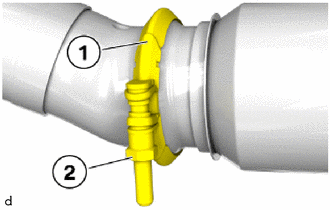
-
Make sure that V-clip (1) is fitted correctly.
Tighten down screw (2).
- Torque:
- 25 N*m (255 kgf*cm, 18 ft.*lbf)
for Ribbon Clamp:
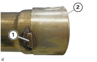
Open the weld seam (1) with a hacksaw.
Remove the exhaust pipe clamp (2).
Replace the exhaust pipe clamp.
Guide in the exhaust pipe assembly with the assistance of a second person and connect it to the exhaust manifold converter sub-assembly.
Tighten the exhaust pipe clamp.
- Torque:
- 26 N*m (265 kgf*cm, 19 ft.*lbf)
Replace nut.
Tighten nut.
- Torque:
- 19 N*m (194 kgf*cm, 14 ft.*lbf)
Check the rubber mounts for damage and replace, if necessary.
Replace nut.
Tighten the nut on the holder.
- Torque:
- 19 N*m (194 kgf*cm, 14 ft.*lbf)
Connect connectors and lock.
58724G
2.INSTALL REAR UNDERBODY PROTECTOR LH
Install the rear underbody protector LH.
Tighten the screws.
- Torque:
- 3.0 N*m (31 kgf*cm, 27 in.*lbf)
58723F
3.INSTALL REAR UNDERBODY PROTECTOR RH
- HINT:
-
Use the same procedure as for the LH side.
58252
4.INSTALL REAR FLOOR PANEL BRACE
- CAUTION:
-
Driving without the rear floor panel brace or rear lower suspension member stopper is not permitted.
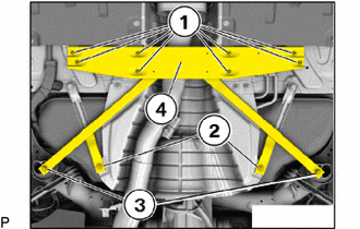
Position the rear floor panel brace (4) and tighten the E14 bolts (3) on the rear lower suspension member stopper.
- Torque:
- 56 N*m (571 kgf*cm, 41 ft.*lbf)
Tighten the bolts (1).
- Torque:
- 28 N*m (286 kgf*cm, 21 ft.*lbf)
Tighten the T20 bolts (2).
- Torque:
- 2.6 N*m (27 kgf*cm, 23 in.*lbf)
57628E
5.INSTALL REAR FLOOR SIDE MEMBER COVER LH
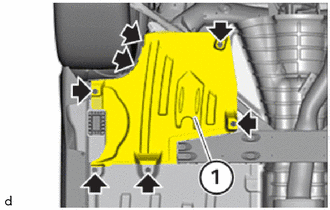
Insert the rear floor side member cover LH (1).
Tighten the screws and plastic nuts.
- Torque:
- Screw : 3.0 N*m (31 kgf*cm, 27 in.*lbf)
- Plastic nut : 2.6 N*m (27 kgf*cm, 23 in.*lbf)
57627G
6.INSTALL REAR FLOOR SIDE MEMBER COVER RH
- HINT:
-
Use the same procedure as for the rear floor side member cover LH.