B48 ENGINE MECHANICAL CYLINDER HEAD INSPECTION
PROCEDURE

 1.INSPECT WATER LEAK
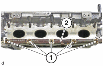
Loosen nuts (1).
Feed out and remove the No.2 turbocharger stay (2).
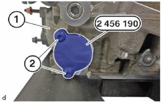
Thread in and install the special tool 2 456 190 on the cylinder head sub-assembly (1).
- SST
- 09200-WA720
Tighten down bolts (2).
- Torque:
- 8.0 N*m (82 kgf*cm, 71 in.*lbf)
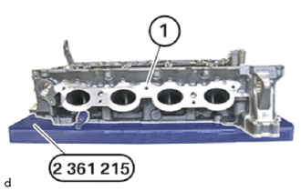
Position the cylinder head (1) on the special tool 2 361 215 so that the rubber layer is pointing towards the cylinder head (1).
- SST
- 09200-WA430
All water ducts on the cylinder head sub-assembly (1) must be closed.
Tighten the cylinder head sub-assembly (1) on the special tool 2 361 215.
- SST
- 09200-WA430
- Torque:
- 35 N*m (357 kgf*cm, 26 ft.*lbf)
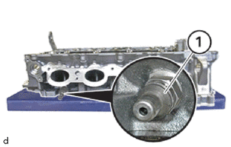
Remove the air by-pass valve assembly (1).
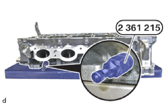
Install the valve of the special tool 2 361 215 on the cylinder head sub-assembly.
- Torque:
- 18 N*m (184 kgf*cm, 13 ft.*lbf)
- SST
- 09200-WA430
Heat up the cylinder head sub-assembly.
- Temperature of the cylinder head:
60 °C (140 °F)
Connect compressed air.
- Maximum Testing Pressure:
300 kPa (3.1 kgf/cm2, 44 psi)
Check the cylinder head sub-assembly in for tightness in a water bath.
Air bubbles develop.
Check cylinder head at the point of exit of the air bubbles for damage, repair or replace if required.
Remove the valve of the special tool 2 361 215.
- SST
- 09200-WA430
Install air by-pass valve assembly (1).
- Torque:
- 18 N*m (184 kgf*cm, 13 ft.*lbf)
Position the No.2 turbocharger stay (2).
Replace nuts (1).
Tighten nuts (1).
- Torque:
- 18 N*m (184 kgf*cm, 13 ft.*lbf)
Loosen bolts (2).
Feed out the special tool 2 456 190 from the cylinder head (1) and remove.
- SST
- 09200-WA720