B58 ENGINE MECHANICAL CYLINDER HEAD INSPECTION
PROCEDURE

 1.INSPECT WATER LEAK
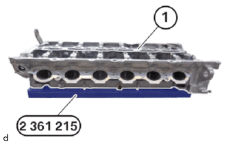
Position the cylinder head sub-assembly (1) on the special tool 2 361 215 so that the rubber layer faces the cylinder head sub-assembly (1) and all water ducts at the cylinder head sub-assembly (1) are closed.
- SST
- 09200-WA430
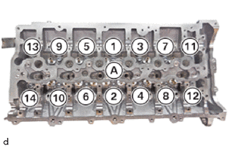
Guide in bolts (1) to (14) on cylinder head sub-assembly (A).
Tighten T60 bolts in the order (1) to (14).
- Torque:
- : 35 N*m (357 kgf*cm, 26 ft.*lbf)
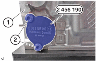
Thread in and install the special tool 2 456 190 on the cylinder head sub-assembly (1).
- SST
- 09200-WA720
Tighten down T30 bolts (2).
Use the bolts of the No. 2 water by-pass hose between the cylinder head sub-assembly and the coolant pump assembly.
- Torque:
- 8.0 N*m (82 kgf*cm, 71 in.*lbf)
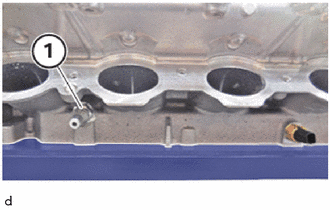
Release air by-pass valve assembly (1).
Guide out and remove air by-pass valve assembly (1).
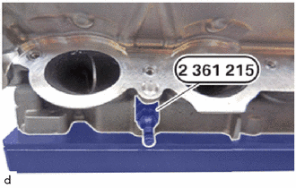
Mount the valve of the special tool 2 361 215 on the cylinder head sub-assembly.
- SST
- 09200-WA430
- Torque:
- 18 N*m (184 kgf*cm, 13 ft.*lbf)
Heat up the cylinder head sub-assembly.
- Temperature of the cylinder head:
60 °C (140 °F)
Connect compressed air.
- Maximum Testing Pressure:
300 kPa (3.06 kgf/cm2, 43.5 psi)
Check the cylinder head sub-assembly in for tightness in a water bath.
Air bubbles develop.
Check the cylinder head sub-assembly for damage at the point of exit of the air bubbles.
Repair or replace the cylinder head sub-assembly if necessary.
Disassemble the valve of the special tool 2 361 215 .
- SST
- 09200-WA430
Install air by-pass valve assembly (1).
- Torque:
- 18 N*m (184 kgf*cm, 13 ft.*lbf)
Loosen bolts (2).
Feed out the special tool 2 456 190 from the cylinder head sub-assembly (1) and remove.
- SST
- 09200-WA720
Release the bolts in the order (14) to (1) from cylinder head sub-assembly (A).
Guide out and remove T60 bolts (14) to (1).
Guide out and remove cylinder head sub-assembly (1) from the special tool 2 361 215 .
- SST
- 09200-WA430