B48 INTAKE / EXHAUST EXHAUST SYSTEM INSPECTION
PROCEDURE

 1. TROUBLESHOOTING ON THE TURBOCHARGER SUB-ASSEMBLY
For charged engines, turbocharger sub-assemblies are of significant importance to the power development. The turbochargers deliver the charging pressure that is required by the engines. Depending on the system (one-phase or multi-phase), one or more turbochargers are installed. However, the function of the turbocharger sub-assembly greatly depends on the proper function of other components in the periphery.
This document describes the sources of faults on the actual turbocharger sub-assembly as well as the factors influencing and causing faults in the periphery.
The following figures show examples of the schematic structure of one-stage or two-stage systems with the required actuators.
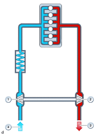
| *1 | Compressor |
| *2 | Turbine |
| *3 | Exhaust gas |
| *4 | Fresh air |
One-phase system
Sectional view of turbocharger sub-assembly
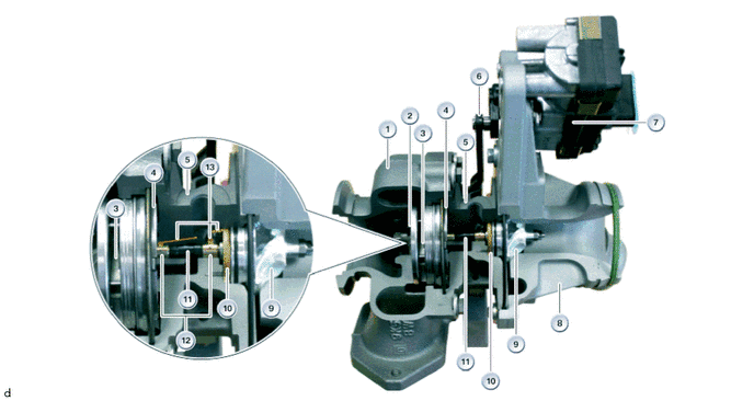
| *1 | Turbine housing | *2 | Turbine wheel |
| *3 | Variable blades | *4 | Adjusting ring |
| *5 | Oil inlet journal | *6 | Adjusting lever |
| *7 | Electrical turbocharger pressure adjuster | *8 | Compressor housing |
| *9 | Compressor | *10 | Thrust bearing |
| *11 | Shaft | *12 | Radial bearing |
| *13 | Oil supply | - | - |
2. GENERAL NOTES ON TROUBLESHOOTING
The following notes must be observed in order to find the root cause of faults when problems are reported, and to prevent the unauthorized, i.e. inappropriate, replacement of the turbocharger sub-assembly:
Tracking down and verifying the complaint
If possible, any problem reported ('complaint') should be tracked down and verified on the vehicle. The parameters or marginal conditions prevailing at the time the problem was reported need to be noted down.
Diagnosis
As a first procedural step, diagnosis must be performed using the diagnosis system.
Faults on sensors and actuators may be responsible for 'complaints', i.e. reported problems, which may also be associated with the turbocharger sub-assembly in some way. For this reason, faults on sensors and actuators must first be remedied if these are stored in the fault memory.
In addition, the engine ventilation is important for the oil supply to the turbocharger sub-assembly. If the pressure in the crankcase is too high, the oil supply to the turbocharger sub-assembly is endangered, and oil leakage may occur at the turbocharger sub-assembly.
The stored charging pressure control faults must then be investigated or troubleshooting must take place on the turbocharger sub-assembly.
Repair history
If possible, check to find out whether repairs have already been made on or near the turbocharger sub-assembly following similar reported problems.
With any repeated complaint with different fault patterns, the problem could have arisen during the last repair.
Problems could have arisen in conjunction with installation, connections or the ingress of foreign bodies.
In the event of identical complaints, it is highly probable that the actual cause of the fault has not been remedied.
3. NOTES ON THE INSTALLATION OF A TURBOCHARGER SUB-ASSEMBLY
Before installation:
Prior to the installation of a turbocharger sub-assembly, fill engine oil in the oil inlet in the turbocharger sub-assembly. At the same time, rotate the shaft on the turbocharger sub-assembly.
Check the oil supply to the turbocharger sub-assembly and the oil return from the turbocharger sub-assembly for foreign bodies and oil sludging, clean if necessary.
Ensure that no dirt and no foreign bodies enter the openings.
Clean the charging air system.
Note: Do not leave any oil residue or foreign bodies in the charge air duct.
Replace gaskets, and ensure that the gaskets are installed correctly.
Observe tightening torques.
After installation:
Start up engine and run it at idle speed for at least one minute to ensure that the turbocharger sub-assembly is receiving a proper oil supply. When the engine is cold and the ambient temperature is low, let the engine idle for approximately 2 minutes.
Check tightness of oil lines.
Stop engine, check oil level.
We can assume no liability for printing errors or inaccuracies in this document and reserve the right to introduce technical modifications at any time.