INTRODUCTION TERMS ABBREVIATIONS USED IN MANUAL
- NOTICE:
-
Contents from preexisting TOYOTA abbreviations and systems have been included as representative examples for their BMW equivalents, and may differ from actual controls and constructions.
- HINT:
-
The search function can be used by simultaneously pressing the Ctrl and F keys on the keyboard.
Abbreviation (include System Name)
| Abbreviations for BMW | Terms of BMW | Abbreviations for TOYOTA | Terms of TOYOTA | Note |
|---|---|---|---|---|
| - | 2-circuit brake system with front/rear split | - | - | Division of the 2-circuit brake system into one brake circuit for the wheel brakes of the front axle and one brake circuit for the rear axle. |
| ABL | Procedure | - | - | Designation of test modules in ISTA. |
| ACC | Active Cruise Control | - | Dynamic Rader Cruise Control System | Abbreviation for the active cruise control with Stop & Go function. |
| ASD | Active Sound Design | ASC | Active Sound Control
Acceleration Sound Control |
The Active Sound Design amplifies the engine sound in the vehicle interior for a sportier impression. |
| AGM | AGM battery | - | Battery | Abbreviation for Absorbent Glass Mat, a special type of lead-acid battery. |
| AKF | Carbon canister | - | Canister (for Emission Control) | Filter for storing fuel vapours. |
| AMPT | Amplifier Top | AMP | Amplifier | The Amplifier Top is the audio amplifier for the highest speaker system equipment. |
| ABS | Antilock Brake System | ABS | Anti-Lock Brake System | Function of the Dynamic Stability Control (DSC) for vehicle stabilisation. |
| ASC | Automatic Stability Control | TRAC/TRC
VSC |
Traction Control System
Vehicle Stability Control |
Function of the Dynamic Stability Control (DSC) for vehicle stabilisation. |
| ADB | Automatic differential brake | TRAC/TRC
LSD |
Traction Control System
Limited Slip Differential |
Function of the Dynamic Stability Control (DSC) for improving the traction. |
| - | Automatic air recirculation control | - | Automatic Recirculation Control | Function of the heating and air conditioning system that assesses the air quality and if necessary automatically changes to the air recirculation function. |
| APIX | Automotive Pixel Link | - | - | Data line for video transmission. |
| BDC | Body Domain Controller | - | Main Body ECU | Central control unit for the vehicle electrical system. Contains the gateway. |
| CID | Central information display | - | Multi-Display | Display in the centre console for the display of the infotainment functions. |
| CCM | Check Control message | - | Warning message | Fault message or warning in the instrument cluster (KOMBI) or on the central information display (CID). |
| CVO | Controlled Valve Operating | - | - | Determination of the actual opening period of the solenoid valve injectors. |
| CON | Controller | - | Remote touch (Remote Operation Controller ASSY) | The controller is the central operating element. |
| CBC | Cornering Brake Control | VSC | Vehicle Stability Control | Function of the Dynamic Stability Control (DSC) for vehicle stabilisation. |
| ACSM | Advanced Crash Safety Module | SRS | Airbag Control Computer | Control unit for passive safety systems, e.g. airbags. |
| D-CAN | Diagnosis-CAN | CAN | Controller Area Network | Bus System. |
| DAB | Digital Audio Broadcast | DAB | Digital Audio Broadcast | Digital radio reception. |
| DME | Digital Motor Electronics | ECM | Engine Control Computer | The Digital Motor Electronics is the engine control unit. |
| DSC | Dynamic Stability Control | - | Skid Control Computer | Central control unit for driving stabilisation. Contains, e.g. the ABS function. |
| DTC | Dynamic Traction Control | TRC | Traction Control | Function of the Dynamic Stability Control, which supports a sportier driving style with restricted driving stability. |
| EBO | Installation location | - | Parts Location | Designation of document type on the topic installation location in ISTA. |
| EPS | Electronic Power Steering | EPS | Electronic Power Steering | Electronic Power Steering is the control unit for the electromechanical power steering. |
| EKP | Electric fuel pump | - | Fuel Pump | Pump for the delivery of the fuel from the fuel tank to the engine. |
| DBC | Dynamic Brake Control | VDIM
VSC |
Vehicle Dynamics Integrated Management
Vehicle Stability Control |
Function of the Dynamic Stability Control (DSC) for vehicle stabilisation. |
| EDC | Electronic Damper Control | AVS | Adaptive Variable Suspension system | The EDC adapts the damping characteristics of the shock absorbers to the current driving situation. |
| EGS | Electronic transmission control | TCM
ECT |
Transmission Control Module
Electronic Controlled Automatic Transmission |
The electronic transmission control is responsible for the activation of the automatic transmission. |
| - | Ethernet switch | - | - | Distributor box for Ethernet. |
| FDR | Driving dynamics control | VSC
ACA |
Vehicle Stability Control
Active Cornering Assist |
Function of the Dynamic Stability Control (DSC) for vehicle stabilisation. |
| - | Remote control receiver | - | Door Control Receiver | The remote control receiver receives the signals from the ID transmitter and forwards them to the Body Domain Controller. |
| FLA | High-beam assistant | AHB | Adaptive High Beam Switch | The high-beam assistant is responsible for the automatic activation of the high beam if no KAFAS camera is installed. |
| - | FlexRay | - | - | Bus System. |
| FLEL | Frontal Light Electronics Left | - | Headlight Control Computer LH | The Frontal Light Electronics Left is responsible for the control of the LED headlight. |
| FLER | Frontal Light Electronics Right | - | Headlight Control Computer RH | The Frontal Light Electronics Right is responsible for the control of the LED headlight. |
| FRS | Front radar sensor | - | Millimeter Wave Radar Sensor | Control unit with integrated radar sensor, which monitors the traffic space in front. |
| FPC | Fuel Pump Controller | - | Fuel Pump Control Computer | Control unit for controlling the electric fuel pump. |
| FUB | Functional description | - | System Description | Designation of document type on the topic component or system function in ISTA. |
| FZD | Roof function centre | - | Map Lamp ASSY | The roof function centre contains the alarm system. |
| GWS | Gear selector switch | - | Transmission Shift Switch ASSY | The drive positions are shifted using the gear selector switch. |
| GHAS | Regulated rear axle differential lock | - | - | The regulated rear axle differential lock adjusts the limited slip differential. |
| HU-B HU-H | Head unit | - | Radio Receiver ASSY
Telematics Transceiver Navigation Computer |
The head unit controls the components in the infotainment area. Depending on the equipment, a Head Unit Basic or a Head Unit High is installed. |
| HRSNL | Rear radar sensor short range left | - | Blind spot monitor sensor rear corner LH (Slave) | Control unit with integrated radar sensor, which monitors the traffic space at the rear left. |
| HRSNR | Rear radar sensor short range right | - | Blind spot monitor sensor rear corner RH (Master) | Control unit with integrated radar sensor, which monitors the traffic space at the rear right. |
| - | ID transmitter | - | Ignition Key (Electrical Key Transmitter SUB-ASSY) | Ignition key. |
| KOMBI | Instrument cluster | - | Combination meter | Control unit with display element, e.g. speed and engine speed. |
| IHKA | Integrated automatic heating /air conditioning | - | Air Conditioning Amplifier ASSY | Control unit for the function of the heating and air conditioning. |
| IBS | Intelligent battery sensor | - | Battery State Sensor | Sensor, which detects the battery data. |
| IROX | IROX coating | - | - | Specially coated bearing shells for connecting rod and crankshaft. |
| - | ITS head airbag | - | SRS Curtain Shield Airbag (Side Airbag) | Inflatable Tubular Structure head airbag. |
| KAFAS | KAFAS control unit | - | Forward Recognition Camera | Control unit with integrated camera, which is responsible for image processing and image evaluation. |
| KAFAS | Camera-based driver assistance systems | RSA
PCS LTA |
Road Sign Assist System
Supplemental Restraint System Lane Tracing Assist System |
Collective term for assistance systems that use the camera function, e.g. lane departure warning. |
| K-CAN. | Body CAN | CAN | Controller Area Network | Bus System. |
| - | Terminal 1 | - | - | Connection designation at ignition coil. |
| 15WUP | Terminal 15 wake-up line | - | - | Terminal that wakes up control units with a voltage signal. |
| - | Terminal 15N | - | - | Switched positive, the N stands for after-run. |
| - | Terminal 30 | - | - | Permanent positive. |
| - | Terminal 30B | - | - | Terminal 30B is used to supply power to control units and components that are required in the presence of the driver during normal operation. |
| - | Terminal 30F | - | - | Terminal 30F is used to supply power to control units and components that require permanent positive during normal operation, but can be switched off in case of a fault. |
| - | Terminal 31 | - | - | Body ground |
| - | Terminal 4a | - | - | Connection designation at ignition coil. |
| LDS | Electric arc wire spraying | - | - | Manufacturing procedure for the coating of the engine cylinders. |
| LIN bus | Local interconnect network bus | LIN | LIN | Single-wire bus. |
| - | Lumbar support | - | Lumbar support | Curvature of the spine to the front. |
| MOST | Media Oriented System Transport | MOST | Media Oriented System Transport | Optical fibre. |
| Automatic start-stop | Automatic engine start/stop function | - | Stop and Start System | Automatic shutdown and start of the petrol engine at vehicle standstill. |
| - | Multi-turn value | - | - | Value for determining the steering angle. |
| NVLD | Natural Vacuum Leak Detection | - | - | Passive on-board-diagnosis for the fuel evaporation system for the leakage test of the fuel tank in US- and Korea-version vehicles. |
| - | OABR Ethernet | - | - | Open Alliance BroadR-Reach. |
| OBD | On-board diagnosis | - | - | Function of the Digital Motor Electronics, which detects and stores faults. |
| Petrol particulate filter | Petrol particulate filter | GPF | Gasoline Particulate filter | Filter for the reduction of the emission of particulate matter in petrol engines. |
| PDC | Park Distance Control | - | Parking Support Brake System | Assistance system, which detects and evaluates the surrounding area of the vehicle by means of ultrasonic sensors and reports the distances to the driver visually and acoustically. |
| PWF | Parking-residing-driving | - | - | Intelligent terminal control. |
| PMA | Parking Manoeuvring Assistant | - | - | Control unit, which is responsible for the evaluation of all ultrasonic sensors. |
| PIB | Pin assignment | - | - | Designation of document type on the topic pin assignment in ISTA. |
| PT-CAN | Powertrain CAN | CAN | Controller Area Network | Bus System. |
| PAD | Check Analysis Diagnosis | - | INSPECTION MODE
MAINTENANCE MODE CERTIFICATION MODE |
All terminals and control units are active. |
| RLSBS | Rain-light-solar-condensation sensor | - | Rain sensor
Light Control sensor |
Sensor at the windscreen, which influences the control of the heating and air conditioning system and the wiper. |
| RDC | Tyre pressure control | TPMS | Tire Pressure Monitoring System | System for monitoring the tyre pressure and the tyre air temperature. |
| RFK | Rear view camera | - | Rear view camera
Back-up Camera |
The rear view camera supports the driver during parking and manoeuvring. |
| - | Safety Systems | - | - | All safety-relevant assistance systems are summarised under the term, such as collision warning, pedestrian warning or lane change warning. |
| - | Safety Systems menu | - | - | Overview and settings menu in the vehicle in which the safety-relevant assistance systems are summarised. |
| SZL | Steering column switch cluster | - | Steering Pad Switch | Control unit, which allows functions of the multifunction steering wheel. |
| - | Safety battery terminal | - | - | The alternator and the starter motor are connected to the safety battery terminal. They are activated in the event of an accident of corresponding severity. |
| SMFA | Driver's seat module | - | Front Power Seat Control System | Control unit for the functions of the driver's seat, e.g. backrest adjustment. |
| STA | Connector view | - | Connector List (Electronic Wiring Diagram) | Designation of document type on the topic connector in ISTA. |
| - | Stop&Go function | - | - | Function within the active cruise control, with which the vehicle can automatically decelerate to a standstill in certain conditions and then automatically drive off again. |
| SSP | System wiring diagram | - | System Circuit (Electronic Wiring Diagram) | Designation of document type on the topic wiring diagram in ISTA. |
| TCB | Telematic Communication Box | - | Telematics Transceiver | The Telematic Communication Box is the control unit for the Toyota Supra Connected services. |
| ISTA | Integrated Service Technical Application | - | - | Workshop system for the diagnosis and programming of the Supra. |
| - | Valvetronic | VVTL-i | Variable Valve Timing and Lift-intelligent | Combination of the variable camshaft timing control (VANOS) and the variable Valvetronic. |
| VANOS | Variable camshaft timing control | VVT-i | Variable Valve Timing-intelligent | Variable adjustment of the valve timings. |
| - | Variable valve lift | - | VALVEMATIC system | Control of the amount of air of the fuel-air mixture on the intake side. |
| VDP | Vertical Dynamic Platform | - | Absorber Control ECU | The control unit Vertical Dynamic Platform controls the Electronic Damper Control. |
| VM | Video module | - | Radio Receiver ASSY | The video module is the TV control unit. |
| WMM | Heat management module | - | - | Electrically driven actuator for controlling the coolant circuits. |
| WCA | Wireless charging station | - | Wireless Charging System | Tray in the centre console, on which a compatible smartphone can be charged wirelessly. |
| ZGM | Central gateway module | - | Central gateway ECU | The central gateway module is an independent control unit in the housing of the Body Domain Controller. The gateway links the different bus systems. |
System Name
| BMW | TOYOTA |
|---|---|
| Park Distance Control | Parking Sensors |
| Intelligent Safety | Toyota Supra Safety |
| Active Cruise Control /Cruise Control (abbr.) | Adaptive Cruise Control |
| High-beam assistant | Automatic high-beam |
| Dynamic brake lamp | Emergency brake lamp |
| Electronic Damping Control | adaptive variable suspension |
| Traction control /Dynamic Traction Control | Traction mode |
| Chassis stabilization /Dynamic Stability Control /DSC /driving stability /Chassis stability /Driving stabilization | chassis stabilization /Dynamic Stability Control /Vehicle Stability Control and Traction control |
| Automatic Start/Stop | Auto Start/Stop |
| Radio Professional, Navigation Business, Navigation Professional, rear-seat entertainment Professional | Multimedia Systems |
| Active PDC | Parking Sensors with emergency braking function |
| Auto PDC /Automatic PDC | Automatic Parking Sensors |
| Comfort access | Comfort entry |
| Comfort access | Smart Key System |
| Automatic Teleservice Call | automatic maintenance call |
| Teleservice | remote maintenance |
| Emergency Request /Emergency call /Emergency | Emergency call |
| Active Blind Spot Detection | Blind spot monitor |
| DSC Dynamic Stability Control | VSC Vehicle Stability Control System |
Information in ISTA (Abbreviation)
| Abbreviation | Information |
|---|---|
| ABL | Procedure (service program) |
| AZD | Tightening torque |
| EBO | Installation location |
| FEB | Fault elimination |
| FTD | Vehicle engineering diagnosis |
| FUB | Functional description |
| IBAC | Internet Based Calculation of Enabling Codes |
| KFA | Function changes to vehicle |
| PIB | Pin assignment |
| REP | Repair instruction |
| SBS | Operating fluids |
| SIT | Service Engineering Information |
| SPI | Vehicle software information |
| SSP | Wiring diagram |
| STA | Connector view |
| SWS | Special Tool |
| SWZ | Special Tool |
| TED | Technical data |
OPERATION AND CONDITION
Terminal Control
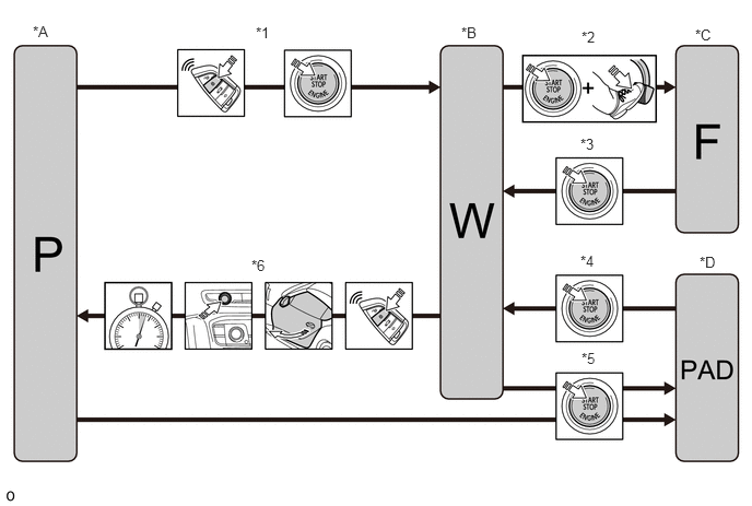
| *A | Parking | *B | Residing |
| *C | Driving | *D | Testing-analysis-diagnosis (PAD) mode |
| *1 | Change from parking to residing.
·
Waking up the vehicle (e.g. vehicle unlocking) ·
Press the start/stop button. |
*2 | Change from residing to driving (combustion engine is started).
·
Press the start/stop button and the brake pedal at the same time. |
| *3 | Change from driving to residing (combustion engine is switched off).
·
Press the start/stop button. |
*4 | Changes from testing analysis-diagnosis (PAD) to residing.
·
Press the start/stop button. |
| *5 | Change to testing-analysis-diagnosis (PAD).
·
Start/stop button is pressed 3 times in 0.8 s. |
*6 | Change from residing to parking.
·
Activate the AUDIO button for more than 3 s. ·
Leaving the vehicle. ·
Lock vehicle. ·
No customer interaction for 10 minutes. |
| States | activated by the following actions: |
|---|---|
| Parking | ·
Customer not in the vehicle ·
Vehicle secured or not used for a certain time ·
Vehicle functions not operable (IG OFF). |
| Residing | ·
Customer in the vehicle ·
Not ready to drive (engine off) ·
Functions that are required when the vehicle is stationary can be operated. |
| Driving | ·
Customer in the vehicle ·
Ready to drive (engine running) ·
All vehicle functions are available. |
| Testing-analysis-diagnosis (PAD) mode | ·
Press the start/stop button 3 times within 0.8 seconds ·
Independent activation during diagnostic test when ISTA is used. |
Power supply
| Conditions | Explanation |
|---|---|
| Terminal 30 | Voltage is always supplied to a specific control unit (antitheft device, etc.), and is not switched OFF even if there is a failure. |
| Terminal 30B | Supplies Power to the necessary control unit when the driver is in the driver's seat. |
| Terminal 30F | Supplies Power to the necessary control unit even when the driver is not in the driver's seat. Possible to stop power supply when there is a failure. |
| Terminal 15N | Supplies power to the necessary control unit for running operations. |
| Terminal 31 | Body ground |
Systems
| Terms | Explanation |
|---|---|
| D-CAN
(Diagnose-on-CAN) |
Responsible for data transfer between the diagnosismaster (gateway) and the diagnosis system. |
| PT-CAN
(PowerTrain CAN) |
Used for networking the control units for the drive and assistance systems. |
| K-CAN | Transfer information from the control units that perform functions in the body area, such as lighting or heating and air-conditioning.
Characteristics of the K-CAN bus systems: ·
2 twisted copper wires ·
Data transfer rate of 500 kBit/s ·
Linear bus structure ·
No emergency running properties. |
| Local-CAN | The following Local-CAN (500 kBit/s) are installed, depending on the equipment specification:
·
Between the rear radar sensor short range right (HRSNR) and rear radar sensor short range left (HRSNL) ·
Between camera-based driver assistance systems (KAFAS) and front radar sensor (FRS). |
| FlexRay | Used in the Supra to ensure networking of the driving dynamics control systems, safety systems and drive systems. |