CRUISE CONTROL MILLIMETER WAVE RADAR SENSOR BEFORE STARTING ADJUSTMENT
PROCEDURE

 1. PRECAUTIONS
- NOTICE:
- ·
Careful attention is necessary when adjusting the millimeter wave radar sensor assembly.
·If the adjustment value of the millimeter wave radar sensor assembly deviates as little as 0.2° relative to the dynamic driving axis, the entire system may be impaired.
2. OVERVIEW OF ADJUSTMENT
- HINT:
- ·
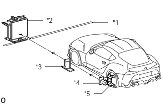 0.573,0.427 0.906,0.427 false 1.948,0.469 2.281,0.469 false 0.948,1.396 1.281,1.396 false 1.75,1.75 2.083,1.75 false 1.979,1.969 2.146,1.969 2.146,1.969 2.313,1.802 false 2.375,0.385 2.688,0.542 0.313,0.156 10 false *1 0.979,0.344 1.292,0.5 0.313,0.156 10 false *2 0.75,1.323 1.063,1.479 0.313,0.156 10 false *3 1.552,1.656 1.865,1.813 0.313,0.156 10 false *4 1.771,1.885 2.083,2.042 0.313,0.156 10 false *5
*1 Rail *2 Setting Device *3 Slotted Cover *4 Wheel Laser *5 Self-Centering Wheel Adapter
In order to adjust the millimeter wave sensor assembly, the mirror surface of the setting device must be positioned so that it is aligned horizontally and vertically with the center line of the vehicle.
·If the setting device cannot be accurately positioned horizontally or vertically relative to the vehicle, the work area itself may not be level. Use the setting device to confirm these deviations.
·The setting device adjustment must be performed for both sides of the vehicle.
·Based on the measured values for both sides of the vehicle, the diagnosis system calculates the correct adjustment values for the setting device.
·By configuring the setting device using the values calculated by diagnosis system, adjustment of the millimeter wave radar sensor assembly can be performed.
3. DESCRIPTION OF SST FUNCTION
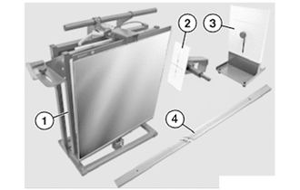
| *1 | Setting Device |
| *2 | Wheel Laser |
| *3 | Slotted Cover |
| *4 | Rail |
Components of SST:
- SST
- 09800-WA150
09800-WA300
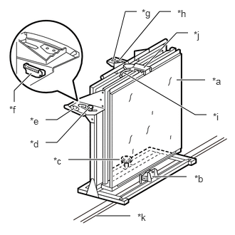
| *a | Mirror |
| *b | Clamp |
| *c | Knurled Screw for Vertical Adjustment of Setting Device |
| *d | Setscrew for Horizontal Mirror Alignment |
| *e | Mirror Horizontal Alignment Scale |
| *f | Spirit Level |
| *g | Knurled Screw for Vertical Mirror Adjustment |
| *h | Mirror Vertical Alignment Scale |
| *i | Clamp Release Locking Lever |
| *j | Tilting Mechanism |
| *k | Rail |
Setting Device:
- HINT:
-
Installing the rail enables the setting device to be set up at a right angle to the vehicle.
Purpose:
Confirming the horizontal and vertical alignment of the vehicle.
Adjusting the millimeter wave radar sensor assembly.
How to install to rail:
Pull the clamp release locking lever to open the clamp.
With the clamp open, place the setting device on the rail.
Release the locking lever to secure the setting device to the rail.
Usage Method:
Setting device main unit angle adjustment:
Use the knurled screw for vertical alignment of the setting device to adjust the setting device main unit so that it is level with the floor.
- HINT:
- ·
Use the spirit level to confirm the angle of the main unit.
·Adjust the unit so that the bubble is in the center of the spirit level.
Mirror angle adjustment:
Use the knurled screw for vertical mirror adjustment to adjust the vertical angle of the mirror.
- HINT:
-
Check the vertical position value of the mirror using the mirror vertical alignment scale.
Loosen the setscrew for horizontal mirror adjustment to adjust the horizontal angle of the mirror.
- HINT:
-
Check the horizontal position value of the mirror using the mirror horizontal alignment scale.
Changing the mirror angle:
Using the tilting mechanism, the mirror angle can be changed through 3 positions.
Rail:
Purpose:
Placed perpendicular to the vehicle, and secures the setting device in place.
Installation Method:
Secure the rail to the floor using duct tape.
- HINT:
-
Secure the rail with duct tape on both sides of the center hole and at both ends of the rail.
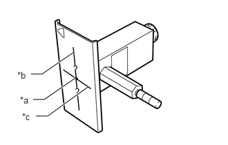
| *a | Laser Beam Emitter Opening |
| *b | Vertical Line |
| *c | Horizontal Line |
Wheel Laser:
Purpose:
The laser beam is projected parallel to the vehicle, and is used in combination with the slotted cover to adjust the mirror angle of the setting device.
Installation Method:
The wheel laser is installed to the rear wheel of the vehicle together with the self-centering wheel adapter.
Usage Method:
Turning on the switch on the back of the unit will project the laser beam.
- CAUTION:
-
Do not look directly into the laser beam.
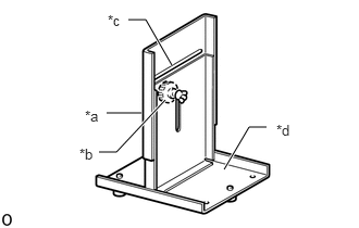
| *a | Height-adjustable Cover |
| *b | Setscrew for Cover |
| *c | Slot |
| *d | Baseplate |
Slotted Cover:
Purpose:
Adjusting the laser beam of the wheel laser so that it is parallel to the floor.
Usage Method:
Placed in front of the wheel laser, the height-adjustable cover and setscrew for cover are adjusted to a height at which the laser beam passes through the slot.
After adjusting the slot height, the slotted cover is moved to a position in front of the front wheel and the laser is passed through the slot again to achieve a laser beam that is parallel to the floor.
- NOTICE:
-
When moving the slotted cover, hold it by the baseplate portion to prevent the adjusted height from becoming misaligned.