CRUISE CONTROL MILLIMETER WAVE RADAR SENSOR ADJUSTMENT
PROCEDURE

 1. BEFORE ADJUSTING MILLIMETER WAVE RADAR SENSOR ASSEMBLY
Preparation:
Check tire pressure and adjust as necessary.
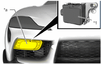
| *1 | Millimeter Wave Radar Sensor Assembly |
| *a | Cover Portion |
Clean away any dirt or foreign matter adhering to the cover of the millimeter wave radar sensor assembly.
Check that there is no damage or deformation around the front exterior area of the vehicle.
Make sure the cover of the millimeter wave radar sensor assembly is clean and has no dirt, snow, or other matter adhering to its surface.
Check that the front bumper assembly and millimeter wave radar sensor assembly installation areas have no damage or deformation.
Secure a work area with a level surface as shown in the illustration.
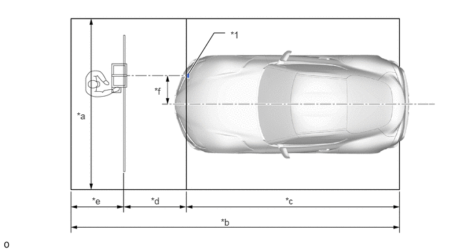
| *1 | Millimeter Wave Radar Sensor Assembly | - | - |
| *a | 400 cm (13.12 ft.) | *b | 675 cm (22.14 ft.) |
| *c | 500 cm (16.4 ft.) | *d | 95 cm (3.12 ft.) |
| *e | 80 cm (2.62 ft.) | *f | 54 cm (1.77 ft.) |
- HINT:
- ·
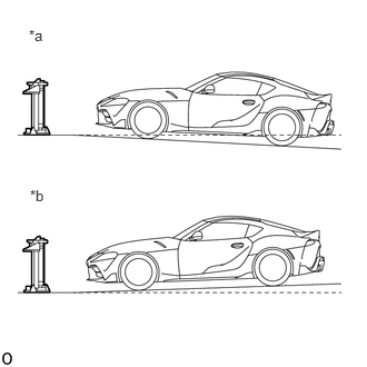 0.271,0.25 0.583,0.406 0.313,0.156 10 false *a 0.281,1.75 0.594,1.906 0.313,0.156 10 false *b
*a Tilt angle of inclined vehicle work area *b Tilt angle of declined vehicle work area
Maximum allowable tilt of work area:
- Standard:
Condition Angle Maximum allowable tilt on an incline 3° Maximum allowable tilt on a decline 1°
Install the rail:
- SST
- 09800-WA300
Set the rail on the floor so that its center hole is aligned with the vehicle centerline.
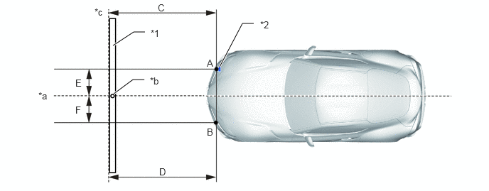
| *1 | Rail | *2 | Millimeter Wave Radar Sensor Assembly |
| *a | Vehicle Centerline | *b | Rail Center Hole |
| *c | Rail Front Edge | - | - |
- NOTICE:
-
The distance (C) from the rail front edge to the millimeter wave radar sensor assembly (A) must be within the range of 95 +/- 10 cm (3.12 +/- 0.33 ft.).
- HINT:
-
The distance (E) from the vehicle centerline to the millimeter wave radar sensor assembly (A) is 54 cm (1.77 ft.).
On the opposite side of the vehicle from point (A), adjust the rail so that the distance (D) from point (B) to the rail front edge is the same as distance (C).
- NOTICE:
- ·
Distance (C) and distance (D) must be the same length.
·Distance (E) and distance (F) must be the same length.
Secure the rail with duct tape on both sides of the center hole and at both ends of the rail.
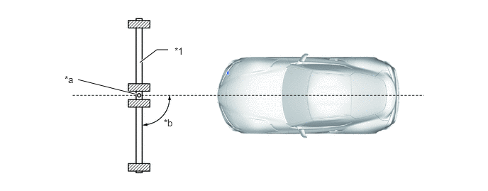
| *1 | Rail | - | - |
| *a | Rail Center Hole | *b | 90° |

|
Duct Tape | - | - |
- NOTICE:
- ·
The rail must be at a right angle to the vehicle.
·If the angle of the rail deviates by 5° or more relative to the vehicle, it will not be possible to adjust the sensors.
- HINT:
-
When securing the rail, clean the surface to which the duct tape will be applied.
2.ADJUST ADJUST SETTING DEVICE (LEFT SIDE)
Install self-centering wheel adapter:
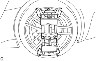
Install the self-centering wheel adapter to the rear left wheel.
- HINT:
-
Check that the center of the self-centering wheel adapter is in the center of the wheel.
Install the wheel laser:
- SST
- 09800-WA150
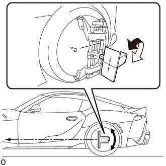
| *a | Setscrew |
Insert the wheel laser into the self-centering wheel adapter.
Adjust the wheel laser so that it is parallel to the floor as much as possible, then tighten the setscrew.
Install the setting device:
- SST
- 09800-WA150
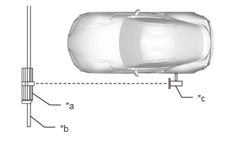
| *a | Setting Device |
| *b | Rail |
| *c | Wheel Laser |
Install the setting device onto the rail directly in front of the wheel laser.
- HINT:
-
Make sure that the setting device is properly secured to the rail.
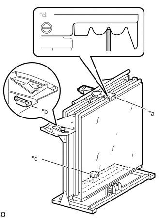
| *a | Tilting Mechanism |
| *b | Spirit Level |
| *c | Knurled Screw for Vertical Adjustment of Setting Device |
| *d | Center Position |
Align the mirror with the center position of the tilting mechanism.
- HINT:
-
The tilt angle can be changed through 3 positions.
Adjust the knurled screw for vertical adjustment of the setting device so that the bubble of the spirit level attached to the setting device is in the center area.
- HINT:
-
The bubble must be in the center area of the spirit level.
Laser beam vertical position adjustment:
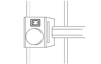
Turn the wheel laser switch on.
- CAUTION:
-
Do not look directly into the laser beam.
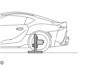
Place the slotted cover on the floor directly in front of the wheel laser.
- SST
- 09800-WA150
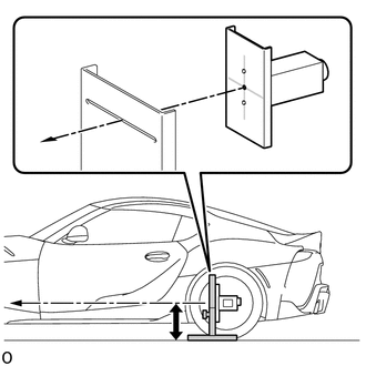
Loosen the setscrew of the slotted cover, adjust the cover height until the laser beam passes through the center of the slot, then tighten the setscrew again.
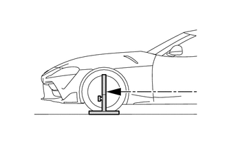
Place the slotted cover on the floor at the center of the front left wheel.
- NOTICE:
-
When moving the slotted cover, hold it by the baseplate portion to prevent the adjusted height from becoming misaligned.
- HINT:
-
Place it within the area where the laser beam is projecting.
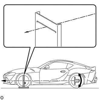
Loosen the setscrew of the wheel laser, adjust the aim of the laser so that the laser beam passes through the center of the slot in the slotted cover, then tighten the setscrew again.
Adjust setting device:
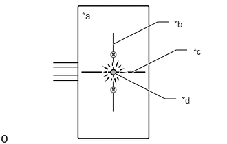
| *a | Projection Surface |
| *b | Vertical Line |
| *c | Horizontal Line |
| *d | Laser Beam Emitter Opening |
Use the following procedure to adjust the angle of the mirror so that the wheel laser beam reflected by the mirror is reflected back close to the laser beam emitter opening.
- Standard:
-1.0 to 1.0 mm (-0.0393 to 0.0393 in.)
- HINT:
-
If the laser beam of the wheel laser is dim, replace the batteries.
Vertical Adjustment:
Using the knurled screw for vertical mirror adjustment, move the mirror vertically so that the reflected laser beam is projected onto the horizontal line of the wheel laser projection surface.
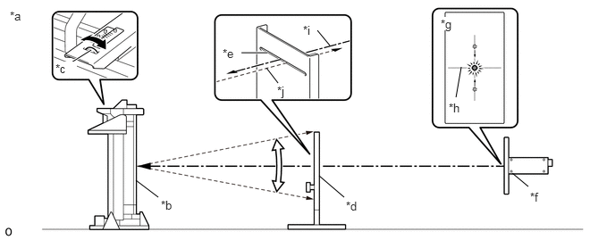
| *a | Side View | *b | Mirror |
| *c | Knurled Screw for Vertical Mirror Adjustment | *d | Slotted Cover |
| *e | Slot | *f | Wheel Laser |
| *g | Projection Surface | *h | Horizontal Line |
| *i | Emitted Laser Beam | *j | Reflected Laser Beam |
- HINT:
-
Adjust the mirror so that the reflected laser beam passes through the slot of the slotted cover again.
Horizontal Adjustment:
Loosen the setscrew for horizontal mirror adjustment, move the mirror horizontally so that the reflected laser beam is projected onto the vertical line of the wheel laser projection surface, then tighten the setscrew again.
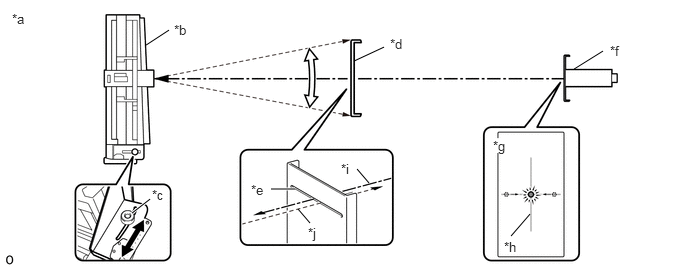
| *a | Top View | *b | Mirror |
| *c | Setscrew for Horizontal Mirror Adjustment | *d | Slotted Cover |
| *e | Slot | *f | Wheel Laser |
| *g | Projection Surface | *h | Vertical Line |
| *i | Emitted Laser Beam | *j | Reflected Laser Beam |
- HINT:
-
Adjust the mirror so that the reflected laser beam passes through the slot of the slotted cover again.
Acquire mirror horizontal / vertical values:
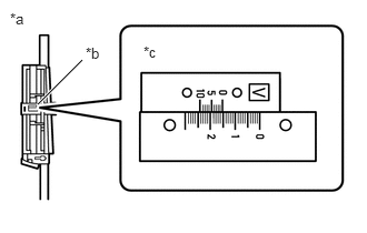
| *a | Example |
| *b | Mirror Vertical Alignment Scale |
| *c | V = 15.2 |
Using the mirror vertical alignment scale, read the vertical position value (V) and write it down.
- NOTICE:
-
When performing the millimeter wave radar sensor assembly adjustment using the diagnosis system the vertical position value must be input, so make sure to write it down.
- HINT:
-
By entering the numerical value that was written down into the diagnosis system, the diagnosis system calculates the necessary vertical values for adjustment of the millimeter wave radar sensor assembly.
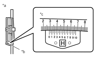
| *a | Example |
| *b | Mirror Horizontal Alignment Scale |
| *c | H = 28.9 |
Using the mirror horizontal alignment scale, read the horizontal position value (H) and write it down.
- NOTICE:
-
When performing the millimeter wave radar sensor assembly adjustment using the diagnosis system the horizontal position value must be input, so make sure to write it down.
- HINT:
-
By entering the numerical value that was written down into the diagnosis system, the diagnosis system calculates the necessary horizontal values for adjustment of the millimeter wave radar sensor assembly.
Remove Wheel Laser:
Turn the wheel laser switch off.
Loosen the setscrew and remove the wheel laser.
Remove self-centering wheel adapter:
Remove the self-centering wheel adapter from the rear left wheel.
3.ADJUST ADJUST SETTING DEVICE (RIGHT SIDE)
- HINT:
-
Use the same procedure as for the LH side.
4.ADJUST MILLIMETER WAVE RADAR SENSOR ASSEMBLY
Install the setting device:
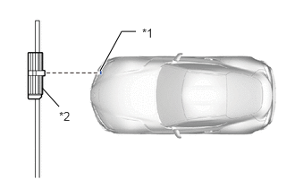
| *1 | Millimeter Wave Radar Sensor Assembly |
| *2 | Setting Device |
Install the setting device onto the rail, centered directly in front of the millimeter wave radar sensor assembly.
- HINT:
-
Make sure that the setting device is properly secured to the rail.
| *a | Tilting Mechanism |
| *b | Spirit Level |
| *c | Knurled Screw for Vertical Adjustment of Setting Device |
| *d | Center Position |
Make sure that the mirror is in the center position of the tilting mechanism.
Adjust the knurled screw for vertical adjustment of the setting device so that the bubble of the spirit level attached to the setting device is in the center area.
- HINT:
-
The bubble must be in the center area of the spirit level.
Using the diagnosis system, enter the following menus:
Vehicle management / Service functions / Driver assistance / Front rader sensor / Front rader sensor: Start-up /ABL Front rader sensor: Start-up
Select [Display].
Following the instructions on the diagnosis system screen, operate the front radar sensor.
Select [Put the front radar sensor (FRS) into operation.] and [Next].
Continue with the steps until [Entering the adjusted vertical value for the left side of vehicle] is displayed on the diagnosis system screen.
At each step, select [Next].
Diagnosis system display: [Entering the adjusted vertical value for the left side of vehicle]
After entering the vertical value measured for the vehicle LH side, select [Next].
- HINT:
- ·
Enter the vertical value that was written down when adjusting the setting device.
·Enter the value to a precision of 0.1 mm (0.0393 in.).
Diagnosis system display: [Confirmation of the entry for the vertical mirror adjustment]
Select [Confirm the entered value.] and [Next].
Diagnosis system display: [Entering the adjusted horizontal value for the left side of vehicle]
After entering the horizontal value measured for the vehicle LH side, select [Next].
- HINT:
- ·
Enter the horizontal value that was written down when adjusting the setting device.
·Enter the value to a precision of 0.1 mm (0.0393 in.).
Diagnosis system display: [Confirmation of the entry for the horizontal mirror adjustment]
Select [Confirm the entered value.] and [Next].
Diagnosis system display: [Base setting of the mirror for the right side of vehicle]
At each step, select [Next].
Diagnosis system display: [Setting the laser pointer for the right side of vehicle]
Select [Next].
Diagnosis system display: [Mirror adjustment for the right side of vehicle]
Select [Next].
Diagnosis system display: [Entering the adjusted vertical value for the right side of vehicle]
After entering the vertical value measured for the vehicle RH side, select [Next].
- HINT:
- ·
Enter the vertical value that was written down when adjusting the setting device.
·Enter the value to a precision of 0.1 mm (0.0393 in.).
Diagnosis system display: [Confirmation of the entry for the vertical mirror adjustment]
Select [Confirm the entered value.] and [Next].
Diagnosis system display: [Entering the adjusted horizontal value for the right side of vehicle]
After entering the horizontal value measured for the vehicle RH side, select [Next].
- HINT:
- ·
Enter the horizontal value that was written down when adjusting the setting device.
·Enter the value to a precision of 0.1 mm (0.0393 in.).
Diagnosis system display: [Confirmation of the entry for the horizontal mirror adjustment]
Select [Confirm the entered value.] and [Next].
Diagnosis system display: [Setting the mirror in front of the front rader sensor (FRS)]
Select [Next].
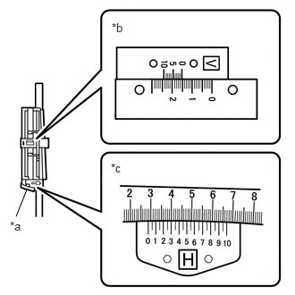
| *a | Setting Device |
| *b | Mirror Vertical Alignment Scale |
| *c | Mirror Horizontal Alignment Scale |
Using the mirror vertical alignment scale and mirror horizontal alignment scale on the setting device, adjust the mirror to the vertical (up/down) and horizontal (left/right) values displayed on the diagnosis system.
After adjusting the mirror, select [Next].
Diagnosis system display: [Mirror alignment completed]
Select [Next].
Diagnosis system display: [Commissioning via the first detent position of the mirror]
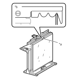
| *a | Tilting Mechanism |
| *b | Front Position |
Adjust the mirror tilting mechanism to the front position.
At each step, select [Next].
Diagnosis system display: [The commissioning for the first detent position was successful.]
Select [Next].
Diagnosis system display: [Commissioning via the second detent position of the mirror]
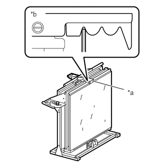
| *a | Tilting Mechanism |
| *b | Rear Position |
Adjust the mirror tilting mechanism to the rear position.
At each step, select [Next].
When setup has completed:
Diagnosis system display: [The commissioning for the front radar sensor (FRS) was successful]
Select [Next].
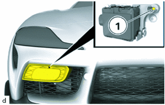
When setup does not complete:
Re-confirm the setting device installation location and work procedures when the adjustments were performed.
If setup still does not complete, perform the following procedures.
Following the instructions on the diagnosis system, use a hexagon wrench (width between flats 3 mm (0.118 in.)) to turn the screw (1) and adjust the millimeter wave radar sensor assembly.
Following the instructions on the diagnosis system, perform the setup again.
Diagnosis system display: [Service function finished]
Select [Next].