B58 INTAKE / EXHAUST TURBO CHARGER ACTUATOR AND LINK INSTALLATION
PROCEDURE

 17240
1.INSTALL TURBOCHARGER ACTUATOR AND LINK ASSEMBLY (for 2 Port Type)
- NOTICE:
- ·
Damage to the turbocharger actuator and link assembly and the mechanical connection.
·Improper handling of the turbocharger actuator and link assembly can lead to malfunctions or failure of the turbocharger actuator and link assembly.
-Avoid exposure of lateral forces to the control rod of the turbocharger actuator and link assembly.
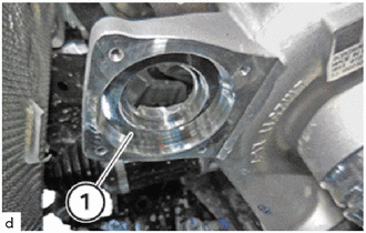
Check contact surface (1) on turbocharger sub-assembly for contamination and clean if necessary.
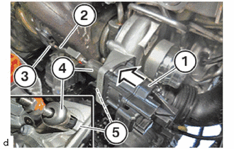
Guide the turbocharger actuator and link assembly (1) into the bore hole of the compressor housing (5) in direction of arrow and position it.
Ensure that the heat shield (4) is positioned correctly on the compressor housing (5).
Carefully install the control rod (2) of the turbocharger actuator and link assembly (1) on the lever of the wastegate valve (3).
- HINT:
-
Any effect of lateral force on the control rod (2) must be avoided.
Replace the T25 bolts.
- HINT:
-
The T25 bolts are included in the repair kit.
Hand-tighten the bolts (1) on the turbocharger actuator and link assembly (2).
Diagonally tighten the bolts (1) on the turbocharger actuator and link assembly (2).
- Torque:
- 2.0 N*m (20 kgf*cm, 18 in.*lbf)
Replace the retaining clip.
- HINT:
-
The retaining clip is included in the repair kit.
Mount the retaining clip.
- HINT:
-
Make sure the retaining clip engages audibly.
Connect and lock the connector.
- HINT:
-
Make sure the connector engages audibly.
17240
2.INSTALL TURBOCHARGER ACTUATOR AND LINK ASSEMBLY (for 6 Port Type)
- NOTICE:
- ·
Damage to the turbocharger actuator and link assembly and the mechanical connection.
·Improper handling of the turbocharger actuator and link assembly can lead to malfunctions or failure of the turbocharger actuator and link assembly.
-Avoid exposure of lateral forces to the control rod of the turbocharger actuator and link assembly.
Check contact surface (1) on turbocharger sub-assembly for contamination and clean if necessary.
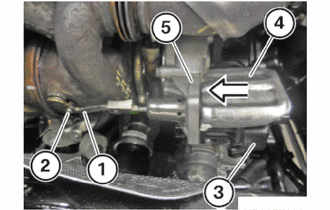
Install the heat shield (4).
Feed electrical wastegate valve controller (3) with the heat shield (4) in the direction of arrow into the bore hole of the compressor housing (5) and position it.
Install the control rod (1) of the electrical wastegate valve controller (3) carefully on the lever of the wastegate valve (2).
- HINT:
-
Any effect of lateral force on the control rod (1) must be avoided.
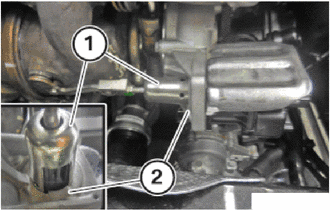
Ensure that the heat shield (1) is positioned correctly on the compressor housing (2).
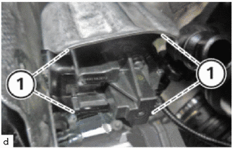
Renew screws (1).
Hand-tighten the screws (1) on the electrical wastegate valve controller.
Diagonally tighten the screws (1) on the electrical wastegate valve controller using the special tool.
- Torque:
- 3.0 N*m (31 kgf*cm, 27 in.*lbf)
Replace the retaining clip.
- HINT:
-
The retaining clip is included in the repair kit.
Mount the retaining clip.
- HINT:
-
Make sure the retaining clip engages audibly.
Connect and lock the connector.
- HINT:
-
Make sure the connector engages audibly.
17240
3.ADJUST TURBOCHARGER ACTUATOR AND LINK ASSEMBLY
Connect the diagnosis system.
12261
4.INSTALL VENTILATION HOSE (for 2 Port Type)
17880
5.INSTALL AIR CLEANER HOSE ASSEMBLY