INTRODUCTION WIRE HARNESS REPAIR WIRE HARNESS REPAIR PROCEDURE
PREPARATORY ITEMS
| llustration | Part number | Part name | Notes and purpose | |
|---|---|---|---|---|
| TOYOTA | BMW
BMW (old) |
|||
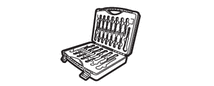
|
09903-WA010 | 83300495382
610300 |
RELEASE TOOL SET | set complete |
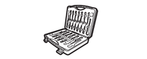
|
09903-WA240 | 83300495407
610329 |
CASE | case with foam material insert not incl. tools |
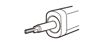
|
09903-WA020 | 83302412134 | RELEASE TOOL | For unlocking the Nano MQS socket housing contacts |
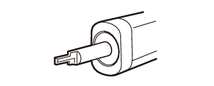
|
09903-WA030 | 83302412135 | RELEASE TOOL | For unlocking the Nano MQS bush contacts |
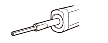
|
09903-WA190 | 83300495406
610324 |
RELEASE TOOL | for secondary lock |
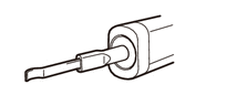
|
09903-WA090 | 83300495394
610312 |
RELEASE TOOL | for flat spring contact with a retaining lug (1.6 mm) |
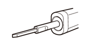
|
09903-WA100 | 83300495395
610313 |
RELEASE TOOL | for flat spring contact swith a retaining tab (1.9 mm) |
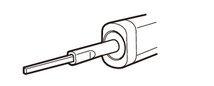
|
09903-WA110 | 83300495396
610314 |
RELEASE TOOL | for flat spring contact with a retaining tab (2.7 mm) |
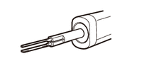
|
09903-WA120 | 83300495397
610315 |
RELEASE TOOL | for flat spring contact swith double retaining tab "Micro-Timer 2") |
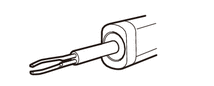
|
09903-WA130 | 83300495398
610316 |
RELEASE TOOL | for flat spring contacts with double retaining tab "SPT 4.8" "JPT 2.8" |
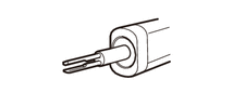
|
09903-WA140 | 83300495399
610317 |
RELEASE TOOL | for LSK 8 |
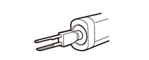
|
09903-WA150 | 83300495400
610318 |
RELEASE TOOL | for "Maxi Power Timer 9.5" |
|
09903-WA160 | 83300495403
610321 |
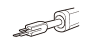
RELEASE TOOL | for sensor laminated contacts with release device ("SLK 2.8") |
|
09903-WA170 | 83300495404
610322 |
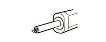
RELEASE TOOL | for mini laminated contact ("MLK 1.2 mm") |
|
09903-WA180 | 83300495405
610323 |
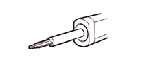
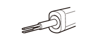
RELEASE TOOL | for flat spring contacts with a retaining tab (MQS) |
|
09903-WA200 | 83300495578
610325 |
RELEASE TOOL | "JPT" |
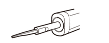
|
09903-WA210 | 83300495676
610326 |
RELEASE TOOL | "MQS" |
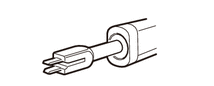
|
09903-WA250 | 83300495680
610331 |
RELEASE TOOL | "SLK 5.8" |
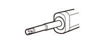
|
09903-WA260 | 83300496332
610332 |
RELEASE TOOL | for unlocking "MQS 0.64 mm" contacts |
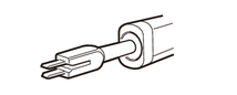
|
09903-WA270 | 83300496333
610333 |
RELEASE TOOL | for unlocking "Mcon 2.8" contacts |
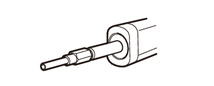
|
09903-WA040 | 83300495383
610301 |
RELEASE TOOL | for round contacts (diameter 1.5) |
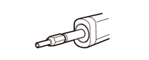
|
09903-WA050 | 83300495385
610303 |
RELEASE TOOL | for round system swith D = 2.5 |
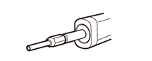
|
09903-WA060 | 83300495387
610305 |
RELEASE TOOL | for round contacts (D = 3.5) |
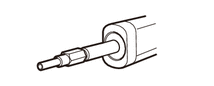
|
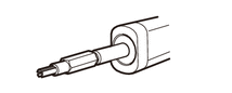
09903-WA070 | 83300495389
610307 |
RELEASE TOOL | for socket-end round contacts (D=1.5) |
|
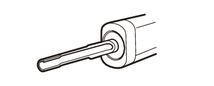
09903-WA080 | 83300495391
610309 |
RELEASE TOOL | for pin-end round contact (D=1.5) |
|
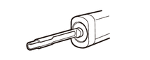
09903-WA220 | 83300495677
610327 |
INSERTION AID | for inserting contacts (0.64 - 1.2 mm) in housing |
|
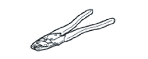
09903-WA230 | 83300495678
610328 |
INSERTION AID | for inserting contacts (2.8 - 4.8 mm) in housing |
|
09929-00020 | - | SST (Crimping tool) S | To crimp sleevesSleeve sizes: SS, S, M |
|
|
09042-2C100 | - | SST (Crimping tool) | To crimp sleeves Sleeve sizes: S, M, L |
|
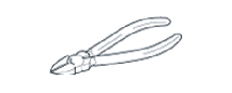
- | - | Wire cutters | To cut wires |
|
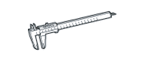
- | - | Caliper | To measure the diameter of a wire and wire strand |
| - | - | - | Dryer or heat gun | To heat heat shrink sleeves (1000W or more, and the thermal fuse with 190°C or more) |
|
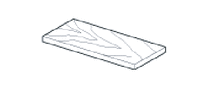
- | - | Wood plate | To shield heat Size reference (mm): 300 x 100 x 10 |
CHECK THE CONNECTOR PART NO., REPAIR WIRE HARNESS PART NO., AND UTILIZED SLEEVE
Check the Connector Information
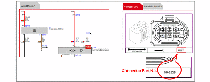
The optional wiring is displayed using Toyota-ISTA.
Check the wiring diagram connector No.
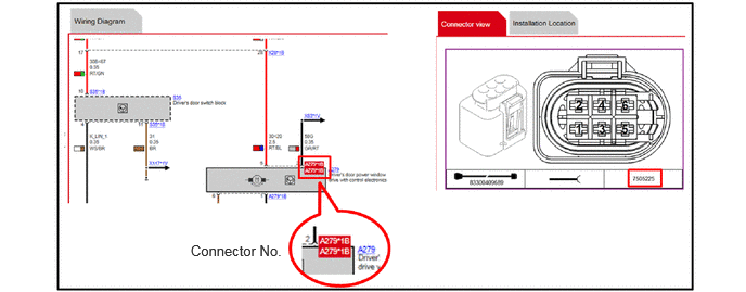
Check the Connectors and Repair Wire Harness Parts No. from the Connector No.
Repair Wire Compatibility List:
Click hereGeneral>INTRODUCTION>WIRE HARNESS REPAIR>CONNECTOR AND REPAIR WIRE COMPATIBLE PART NUMBER LIST
- NOTICE:
- ·
Nos. displayed in the bottom right of the illustration are control numbers within BMW.
·The Control number within BMW is not the Connector Number.
- HINT:
-
-
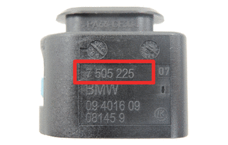
Confirmation method if the Part No. is printed on the connector:
- 1.
Read the part no. printed on the connector.
2.Check the Connector and Repair Wire Harness Part Nos. from part no. read.
Click hereGeneral>INTRODUCTION>WIRE HARNESS REPAIR>CONNECTOR AND REPAIR WIRE COMPATIBLE PART NUMBER LIST
- NOTICE:
- ·
Part Nos. are not always printed to all connectors.
·Since connectors equipped on the vehicle and supplied connectors do not necessarily have the same part nos., it is possible that a search cannot be done in part no. searching.
Check the sleeve used
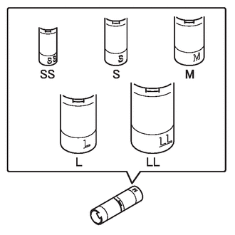
Sleeves
When two wires are joined using a sleeve, select the appropriate sleeve by referring to the table shown on the right.
Nominal wire size and sleeve size
| Nominal wire size
(mm2) |
Sleeve size
(Color) |
|---|---|
| 0.5 | SS (Silver) |
| 0.75-1.0 | S (Silver) |
| 1.25-2.5 | M (Silver) |
| 3.0-5.0 | L (Silver) |
| 8.0 | LL (Silver) |
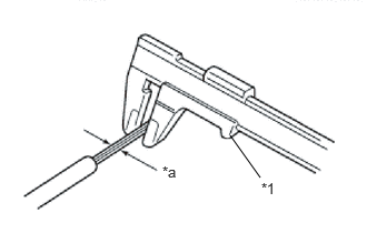
| *1 | Calipers |
| *a | Diameter of Wire Lead |
To calculate the "Nominal Size" of the wire
Nominal size = 3.14 x (Diameter of wire lead)2 / 4
Representative terminal and connector
A representative example is listed in this item.
- Manufactured by AMP:
The following contact types without strand sealing can be fitted in the sokethousings:
MQS (Micro Quadlock System)
MPQ, width 2.8 mm (Micro Power Quadlock)
MPQ, width 5.2 mm (Micro Power Quadlock)
- Manufactured by Siemens:
The following contact types without strand sealing can be fitted in the sockethousings:
Elo (electrical contact)
Elo Power 2.8 mm width (electrical contact for heavy loads)
Elo Power 5.2 mm width (electrical contact for heavy loads)
Connector structure for each terminal type
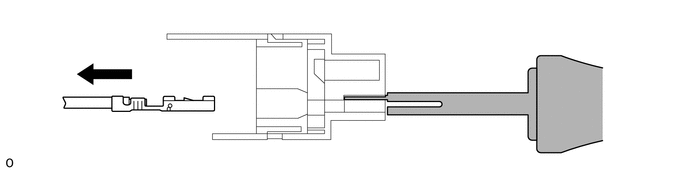
Flat terminal systems with 1 locking tab
Secondary lock
If necessary remove spacer or unlock secondary lock(s) using the appropriate tool.
Primary lock
If necessary remove spacer or unlock secondary lock(s) using the appropriate tool.
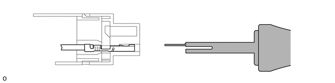
Push the terminal simultaneously into the locking lance.
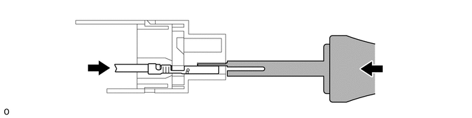
Pull the terminalout of the connector by using lead.
Flat terminal systems with 2 locking tabs
Secondary lock
If necessary remove spacer or unlock secondary lock(s) using the appropriate tool.
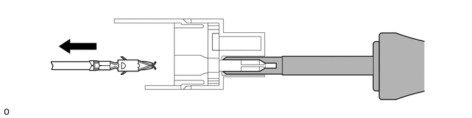
Primary lock
Insert the tool into the locking lance.
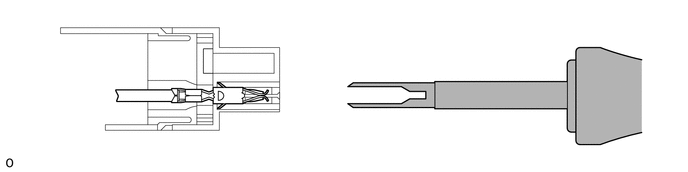
Grasp the lead and push the terminal in order to rase the lock tang of the connector shoulder.
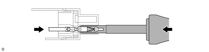
Pull the terminal out of the connector by using the lead.
Pound terminal systems
Secondary lock
If necessary remove spacer or unlock secondary lock(s) using the appropriate tool.
Primary lock
Insert the tool into the locking lance.
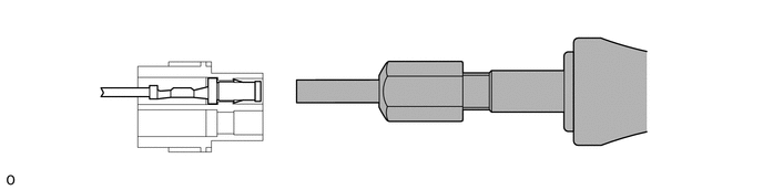
Push handle through, grasp the lead and push the terminal.
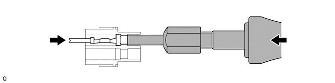
Terminal is ejected.
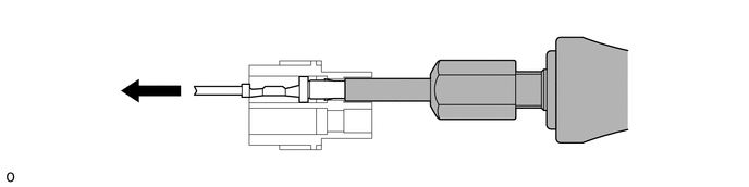
Asymmentrical flat terminal systems
Secondary lock
If necessary remove spacer or unlock secondary lock(s) using the appropriate tool.
Primary lock
Insert the tool into the locking lance
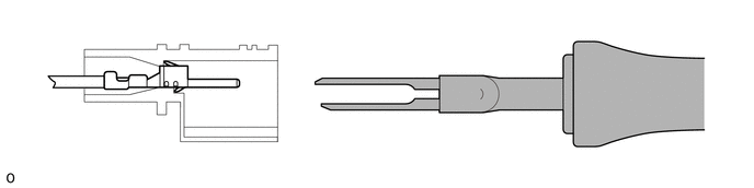
Grasp the lead and push the terminal in order to rase the lock tang of the connector shoulder.
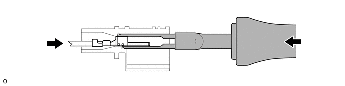
Pull the terminal out of the connector by using the lead.
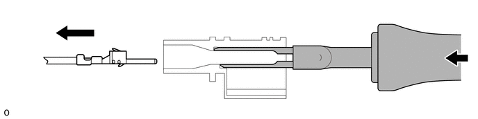
Flat terminals SLK 2.8 mm
SLH 2.8 mm housing without secondary lock
Insert the tool into the locking lances and push handle through.
Terminal is ejected.
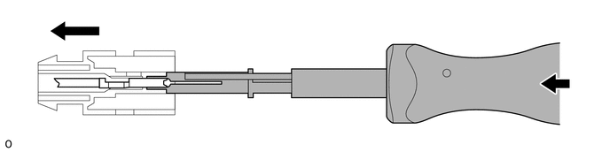
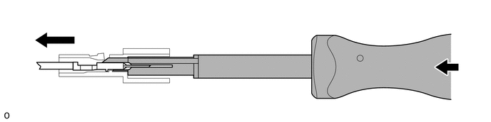
SLH 2.8 mm housing with secondary lock
Insert the tool into the locking lance.
Push the lead with your finger into the toolblade.
Connector structure for special types and terminal removal methods
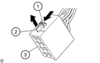
Type A
Type 1:
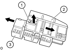
Press locks (1) on protective cap (2) upwards on both sides.
Detach protective cap from contact carrier (3).
- HINT:
-
Detaching the protective cap releases the secondary locks of the socket contacts.
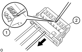
Hold down retaining hook (1) of socket contact in opening of contact carrier with a small screwdriver. Pull wire with socket contact in direction of arrow as far as secondary lock (2).
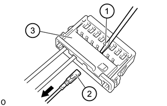
Hold down retaining hook in secondary lock (1) again and pull cable with socket contact (2) completely out of contact carrier (3).
Type 2:
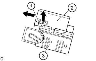
Press locks (1) on protective cap (2) upwards on both sides.
Detach protective cap from housing carrier (3).
- HINT:
-
Detaching the protective cap releases the secondary locks of the pin contacts in the contact carriers.
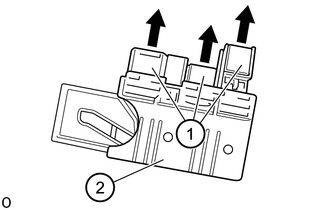
Pull contact carrier (1) out of housing carrier (2).
The pin contacts are pulled out of a contact carrier as described under "Socket housing".
Type B
SST: 61 0 316
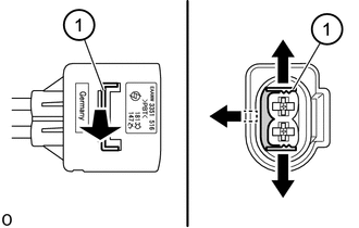
Unlock lock (1) on outside at retaining hook and slide out lock (1) to side.
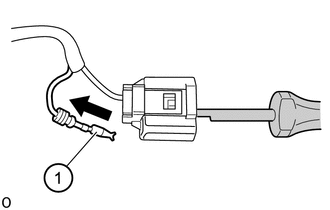
With SST unlock contact and pull out cable with contact (1) towards rear.
Type C
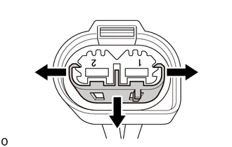
Press catch on outside in direction of arrow and remove towards top.
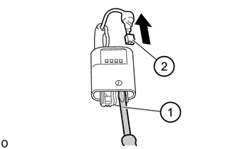
Press down retaining hook (1) with screwdriver and pull out cable and contact (2) towards rear.
Type D
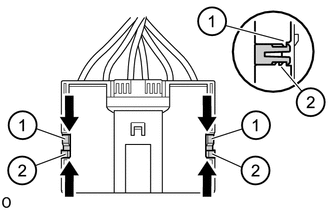
Press locking hook (1) in direction of arrow and disengage. Then unlock locking hook (2) and remove lock.
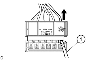
Press down retaining hook with screwdriver (1) and pull out cable with contact towards rear.
Type E
SST: 61 0 316
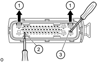
Open secondary locks (1) on socket housing.
Press back retaining hook of MQS contacts (2) with SST and pull out cable with contact.
Press back retaining hook of MPQ contacts (3) with screwdriver and pull out cable with contact.
Type F
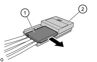
Detach fastener (1) from contact carrier (2).
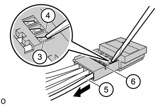
Hold down retaining hook (3) of defective contact and pull cable and contact up to secondary lock (6).
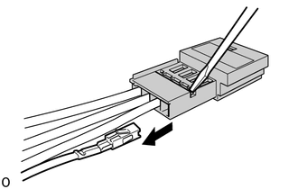
Hold down retaining hook once again in secondary lock and pull cable and contact completely out of contact carrier.
Type G
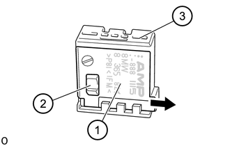
Type 1:
Raise fastener (1) over retaining lug (2) and pull off from contact carrier (3).
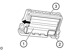
Type 2:
Raise fastener (1) over retaining lug (2) and pull off from contact carrier (3).
Hold down retaining hook (1) of contact and pull cable with contact as far as secondary lock (2).
Hold down retaining hook in secondary lock (1) again and pull cable with contact (2) completely out of contact carrier (3).
Type H
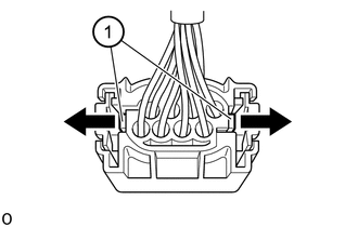
Press lock (1) in direction of arrow and slide connector forward.
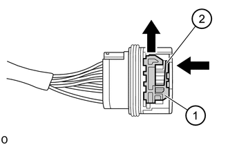
Press locking hook (2) downward and slide lock (1) out.
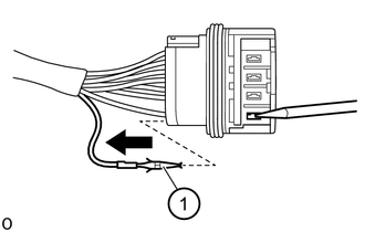
Press down retaining hook (1) with screwdriver and pull out cable with contact towards rear.
Type I
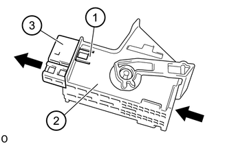
Raise lock (1) on housing (2). Push contact carrier (3) from rear out of housing.
- HINT:
-
The second contact carrier is pushed out in the same way.
Pushing out the contact carrier releases the secondary locks of the socket contacts.
Hold down retaining hook (1) of socket contact in opening of contact carrier with a small screwdriver.
Pull wire with socket contact in direction of arrow as far as secondary lock (2).
Hold down retaining hook in secondary lock (1) again and pull cable with socket contact (2) completely out of contact carrier (3).
Type J
SST: 61 0 314
Type 1:
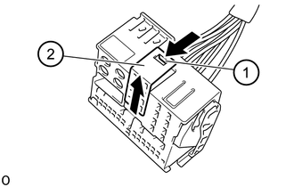
Press lock (1) in direction of arrow.
Detach secondary lock (2) from radio plug.
Feed SST past side of contact.
Press SST in direction of arrow.
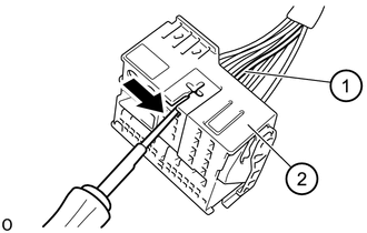
Pull wire (1) with socket contact out of radio connector (2).
Type 2:
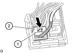
Press lock (1) in direction of arrow and pull housing (2) out of radio connector.
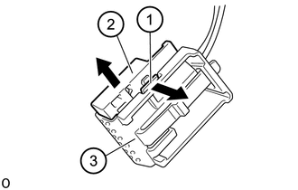
Press lock (1) in direction of arrow. Pull contact carrier (2) out of housing (3).
- HINT:
- ·
When the contact carrier is pulled out, the secondary locks of the socket contacts are raised.
·Schematic diagram shows the 8-pin socket housing by way of example.
Hold down retaining hook (1) of socket contact in opening of contact carrier with a small screwdriver.
Pull wire with socket contact in direction of arrow as far as secondary lock (2).
Hold down retaining hook in secondary lock (1) again. Pull wire with socket contact (2) out of contact carrier (3).
Type 3:
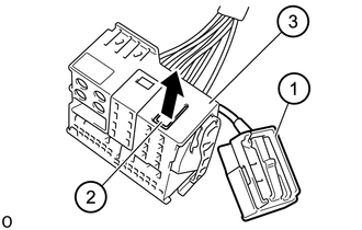
Remove contact carrier (1) with MQS contacts from radio connector.
Raise lock (2) on radio connector.
Pull contact carrier (3) out of radio connector.
Press lock (1) in direction of arrow.
Pull secondary lock (2) in direction of arrow completely out of contact carrier (3).
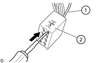
Press SST on inside of contact into contact carrier (2).
Pull wire with socket contact (1) out of contactcarrier (2).
Type K
SST: 61 0 317
Type 1:
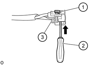
Press lock (1) with suitable tool (2) in direction of arrow out of socket housing (3).
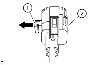
Pull lock (1) out of socket housing (2).
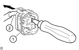
Insert SST into socket housing (1) and pull out wiring with LCC contact (2) in direction of arrow.
Type 2:
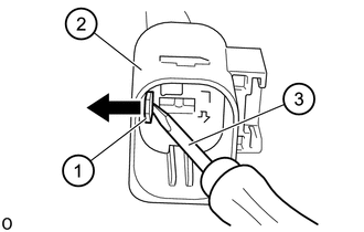
Unlock locking slide (1) of pin housing (2) with suitable tool (3) in direction of arrow.
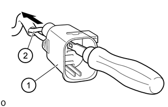
Insert SST into pin housing (1) and pull out wiring with LCC contact (2) in direction of arrow.
Type L
SST: 61 0 303
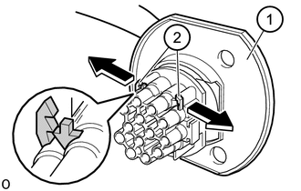
Pull off rubber grommet (1). Carefully pull out lock (2) in direction of arrow.
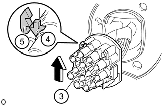
Move lower section of connector (3) in direction of arrow until retaining lugs (4) snap into release groove (5).
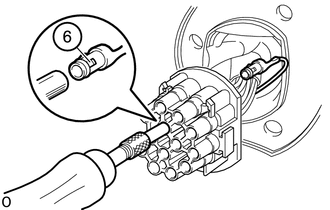
With SST press down retaining lugs (6) of corresponding contact and pull out cable.
Type M
SST: 61 0 333
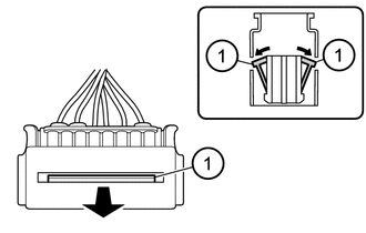
Press locking hook (1) in direction of arrow and disengage.
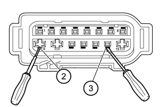
Press back retaining hook of contacts (2) with SST and pull out cable with contact.
Press back retaining hook of contacts (3) with screwdriver and pull out cable with contact.
Replace the wire terminal
Use the new wire lead as a guide for proper length.
- HINT:
- ·
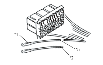 0.646,1.177 0.917,1.417 false 2.063,1.385 2.49,1.635 false 2.063,1.594 2.313,1.865 false 0.479,1.083 0.792,1.281 0.313,0.198 10 false *1 2.323,1.865 2.635,2.063 0.313,0.198 10 false *2 2.531,1.583 2.844,1.781 0.313,0.198 10 false *a
*1 Existing terminal *2 Repair wires *a Cut
If the length of wire removed is not approximately the same length as the new piece, the following problems may develop:
-Too short - tension on the terminal, splice, or the connector, causing and open circuit.
-Too long - excessive wire near the connector, may get pinched or abraded, causing a short circuit.
·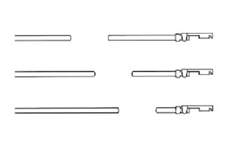
When connecting a wire harness at there or more spots to the same connector, cut the wire harness as shown on the right.
Remove the sheaths from the existing wire and the repair terminal wire.
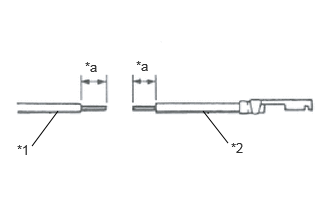
| *1 | Existing Harness |
| *2 | Repair wires |
| *a | 8-11 (mm) |
Start stripping at least 8 mm to 11 mm away from the end of the existing harness at vehicle side and also from the end of the repair wire.
- NOTICE:
-
Good Example
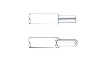
Bad Example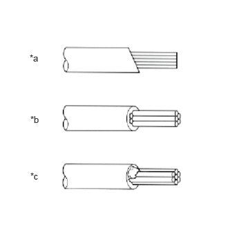 0.448,0.792 0.76,0.99 0.313,0.198 10 false *a 0.458,1.719 0.771,1.917 0.313,0.198 10 false *b 0.458,2.573 0.771,2.771 0.313,0.198 10 false *c
*a Wire insulation stripped st a Slant *b Wire Lesd is Cut *c Insulation Remains on the Lead
-
Do not damage or cut the wire strand. After the sheath is removed, visually check the wire. If any damage is found, do the sheath removal again.
Select Correct Size of Sleeve from the Supply Parts.
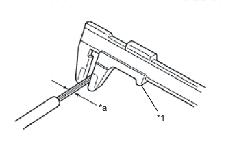
| *1 | Calipers |
| *a | Diameter of Wire Lead |
Using a caliper, measure the outer diameter of the wire or the diameter of the wire strand.
- HINT:
-
To calculate the "nominal size" of wire
-
Nominal size = 3.14 x (Diameter of wire lead)2 / 4
Use the table to determine proper sleeve size.
| Sleeve size | Part number | Nominal wire size
(mm2) |
|---|---|---|
| SS | 82999-50010 | 0.5 |
| S | 82999-52010 | 0.75-1.0 |
| M | 82999-52020 | 1.25-2.5 |
| L | 82999-30020 | 3.0-5.0 |
| LL | 82999-60020 | 8.0 |
Join the strands of the existing wire and new terminal wire.
- NOTICE:
-
If unauthorized work procedures, crimping tools or sleeves are used in aluminum wires repair, an improper wire connection may occur.
Using the table shown below, confirm the appropriate sleeve size and crimp size.
| Sleeve size | Crimp size | Crimp mark |
|---|---|---|
| SS | 0.5 | 0 |
| S | 1.25 | 1 |
| M | 2 | 2 |
| L | 5.5 | 5 |
| Part name | Part number |
|---|---|
| SST(Crimping tool) S | 09929-00020 |
| SST(Crimping tool) | 09042-2C100 |
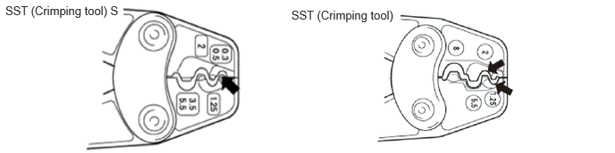
Squeeze the tool handles to disengage the ratchet.
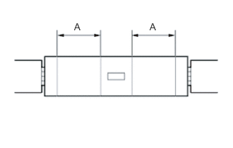
Place the sleeve in the crimping area of the tool, and hold the tool handles to hold the sleeve.
- HINT:
-
Hold area A shown in the illustration.
- NOTICE:
-
Ensure that the protrusion of the tool's crimping portion will come into contact with the seam of the sleeve.
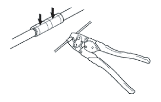
Insert the wire into the sleeve as far as it can go.
Squeeze the tool handles until the ratchet disengages again.
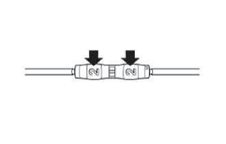
Check that the crimp mark is correct.
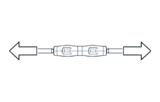
Pull the connected wires to check that they have been connected securely.
- NOTICE:
-
If the connected wire(s) is pulled out from the crimped sleeve or crimping has failed, replace the sleeve with a new one and then crimp again.
Waterproof and insulate the joint area
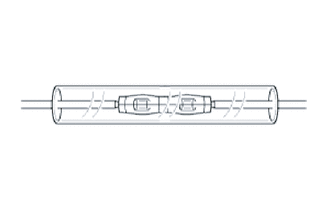
Cover the joints with heat shrink sleeves, and position the joints at the center of the sleeves.
| Part name | Part number |
|---|---|
| Heat shrink sleeve | 82999-30010 |
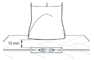
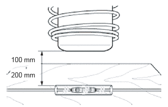
Using a dryer or heat gun, apply hot air to a heat shrink sleeve for about 10 seconds.
- HINT:
- ·
When a dryer is used, keep it about 10 mm away from the shrink sleeve.
·When a heat gun is used, keep it 100 to 200 mm away from the shrink sleeve.
- NOTICE:
-
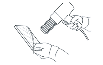
- ·
Use a wood plate to prevent hot air from being applied to other wires.
·Be careful when using a dryer or heat gun. Otherwise burn injuries may result.
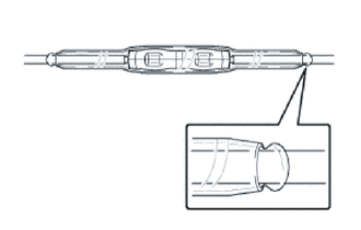
Turn off the dryer or heat gun, and check if a resin substance has come out of the gap between the shrink sleeve and wire at each sleeve end. Repeat step (b) described above until resin substances come out.