 |
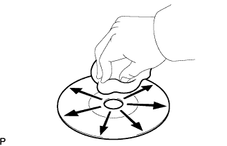
If the disc gets dirty, clean the disc by wiping the surface from the center to the outside, in a radial direction, with a soft cloth as shown in the illustration.
- NOTICE:
- Do not use a conventional record cleaner or anti-static preservative.
AUDIO AND VISUAL SYSTEM > SYSTEM DESCRIPTION |
| COMPACT DISC PLAYER |
Compact Disc (hereafter called CD) players use a laser beam pick-up to read the digital signals recorded on CDs and reproduce analog signals of the music etc. 4.7 in. (12 cm) and 3.2 in. (8 cm) discs are available for the CD player.
| MAINTENANCE CD Player/Disc Cleaning |
|
If the disc gets dirty, clean the disc by wiping the surface from the center to the outside, in a radial direction, with a soft cloth as shown in the illustration.
| OUTLINE OF AVC-LAN |
What is AVC-LAN?
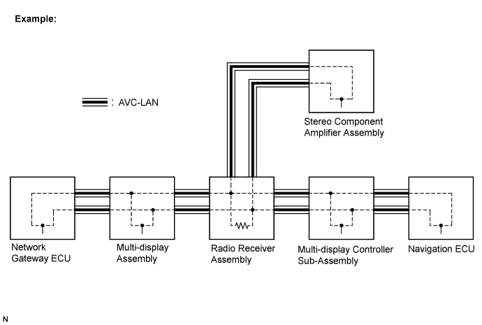
AVC-LAN is an abbreviation for Audio Visual Communication-Local Area Network. This is a unified standard co-developed by 6 audio manufacturers associated with Toyota Motor Corporation. The unified standard includes signals, such as audio, visual and signals for switch indication and communication.
Objectives
Recent development in car audio systems has been rapid and functions have been changed drastically. The conventional system has been switched to a multi-media type such as the navigation system. At the same time customers want to upgrade their audio systems. This is the factor that lies behind this standardization.
The concrete objectives are explained below.
When products of different manufacturers are combined together, malfunctions such as sound failure can occur. This problem can be solved by the standardization of signals.
Various types of after market products are available.
In general, new products developed by particular manufacturers could not be used due to a lack of compatibility with other manufacturer's products. By developing this new standard, users can enjoy a range of compatible products from different manufacturers.
| COMMUNICATION SYSTEM |
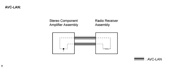
Components in the audio system communicate with each other through the AVC-LAN. (Radio receiver with CD changer control function)
When a short circuit or circuit breakdown occurs in the AVC-LAN circuit, the audio system does not operate normally due to the communication cutoff.
| DIAGNOSTIC FUNCTION |
The audio system has a diagnostic function (the diagnostic result is displayed on the LCD of the radio receiver assembly). (Radio receiver with CD changer control function)
The component code (physical address), or three-digit number (in hexadecimal) is set for each component comprising AVC-LAN.
The logical address, or two-digit number (in hexadecimal) is set for each function and component unit in each component.
| DIAGNOSTIC TROUBLE CODE CHART |
| Terms | Description |
| Physical address | Three-digit code (shown in hexadecimal) which is given to each component comprising AVC-LAN. Corresponding to the function, individual symbols are specified. |
| Logical address | Two-digit code (shown in hexadecimal) which is given to each function comprising inner system of AVC-LAN. |
190 (RADIO RECEIVER ASSEMBLY)
| DTC | Diagnosis Item | Diagnostic Content | Troubleshooting |
| D5 *1 | Registered Component Disconnected | Component shown by sub code is or was disconnected from system with ignition switch in ACC or ON. Communication with component shown by sub code is not ensured when engine is started. |
|
| D6 *1 | Absence of Master | Component in which this code is recorded was disconnected from system or master component with ignition switch in ACC or ON. |
|
| D7 *5 | Connection Check Error | Component in which this code is recorded was disconnected from system or master component with ignition switch in ACC or ON. |
|
| D8 *2 | No Response to Connection Check | Component shown by sub code is or was disconnected from system after engine start. |
|
| D9 *1 | Last Mode Error | Audio or visual component operated before engine stop is or was disconnected with ignition switch in ACC or ON. |
|
| DA | No Response to ON/OFF Instruction | No response is identified when changing mode (audio and visual mode change). Sound and picture do not change by button operation. |
|
| DB *1 | Mode Status Error | Dual alarm is detected. |
|
| DC *3 | Transmission Error | Transmission to component shown by sub code has failed. (Detecting this DTC does not necessarily mean actual failure.) | If same sub code is recorded in other component, check harness for power supply and communication systems of all components shown by code. (If not, delete DTC and recheck.) |
| DD *4 | Master Reset (Momentary Interruption) | After engine was started, master component was disconnected from system. |
|
| DE *4 | Slave Reset (Momentary Interruption) | After engine was started, component shown by sub code was disconnected from system. |
|
| DF *4 | Master Error | Due to defective condition of component with display, master function is switched to audio equipment. |
|
| E0 *1 | Registration Completion Instruction Error | Registration completion instruction command from master cannot be received. | Since this DTC is provided for engineering purposes, it may be set when no actual failure exists. |
| E1 *1 | Voice Processing Device ON Error | Amp device records that amp output does not function even while source device is operating. |
|
| E2 | ON/OFF Instruction Parameter Error | Error occurs in ON/OFF controlling command from master component. | Replace radio receiver assembly. |
| E3 *1 | Registration Request Transmission | Registration request command is output from component shown by sub code. Receiving connection check instruction, Registration request command is output from sub-master component. | Since this DTC is provided for engineering purposes, it may be set when no actual failure exists. |
| E4 *1 | Multiple Frame Abort | Multiple frame transmission is aborted. | Since this DTC is provided for engineering purposes, it may be set when no actual failure exists. |
| 22 | RAM Error | Abnormal condition of RAM is detected. | Replace radio receiver assembly. |
| DTC | Diagnosis Item | Diagnostic Content | Troubleshooting |
| 42 | No Disc Readout | Disc cannot be read. |
|
| 44 | CD player Error | Error is detected in CD player. | Replace radio receiver assembly |
| 45 | EJECT Error | Disc cannot be ejected. | Replace radio receiver assembly |
| 46 | Disc has scratches on the reverse surface | CD has dirt or scratches on reverse side. |
|
| DTC | Diagnosis Item | Diagnostic Content | Troubleshooting |
| 42 | No Disc Readout | Disc cannot be read. |
|
| 44 | CD player Error | Error is detected in CD player. | Replace radio receiver assembly |
| 45 | EJECT Error | Disc cannot be ejected. | Replace radio receiver assembly |
| 46 | Disc has scratches on the reverse surface | CD has dirt or scratches on reverse side. |
|
| 51 | Elevator Error | Mechanical error occurred during elevator operation. | Replace radio receiver assembly |
| 52 | Clamp Error | Error occurs on clamp | Replace radio receiver assembly |
440 (STEREO COMPONENT AMPLIFIER ASSEMBLY)
| DTC | Diagnosis Item | Diagnostic Content | Troubleshooting |
| D6 *1 | Absence of Master | Component in which this code is recorded was disconnected from system with ignition switch in ACC or ON. Alternatively radio receiver assembly was disconnected when this code was recorded. |
|
| D7 | Communication Check Error | Component in which this code is recorded is or was disconnected from system after engine start. Alternatively radio receiver assembly was disconnected when this code was recorded. |
|
| DC *2 | Transmission Error | Transmission to component shown by sub code has failed. (Detecting this DTC does not necessarily mean actual failure.) | If same sub code is recorded in other component, check harness for power supply and communication systems of all components shown by code. (If not, delete DTC and recheck.) |
| DD *3 | Master Reset (Momentary Interruption) | After engine was started, master component was disconnected from system. |
|
| DD *4 | Master Error | Due to defective condition of component with display, master function is switched to audio equipment. Error occurs in communication between sub-master (audio) and master component. |
|
| E0 *1 | Registration Completion Instruction Error | Registration completion instruction command from master cannot be received. | Since this DTC is provided for engineering purposes, it may be set when no actual failure exists. |
| E1 *1 | Audio processor ON Error | While source device is operating, amp output stops. |
|
| E2 | ON/OFF Instruction Parameter Error | Error occurs in ON/OFF controlling command from master component. | Replace radio receiver assembly. |
| E3 *1 | Registration Request Transmission | Registration request command is output from slave component. | Since this DTC is provided for engineering purposes, it may be set when no actual failure exists. |