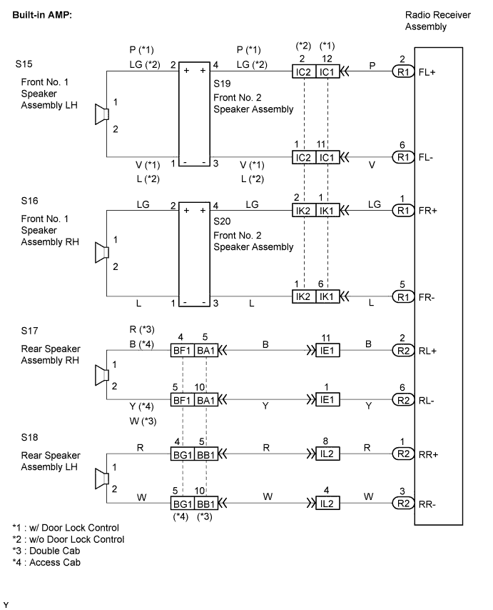
AUDIO AND VISUAL SYSTEM > Speaker Circuit |
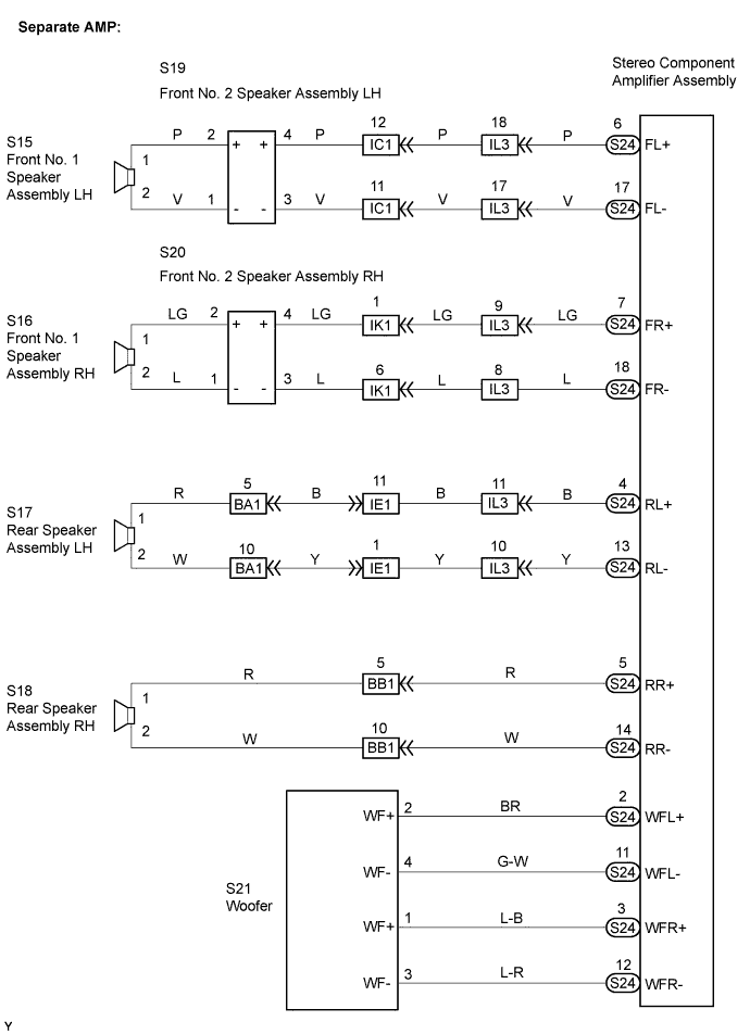
| 1.SYSTEM CHECK |
Check the system.
Check whether the stereo component amplifier assembly is a built-in type or a separate type.
| Amplifier Type | Proceed To |
| Built-in AMP | A |
| Separate AMP | B |
|
| ||||
| A | |
 |
| 2.CHECK HARNESS AND CONNECTOR (RADIO RECEIVER ASSEMBLY - SPEAKER ASSEMBLY) |
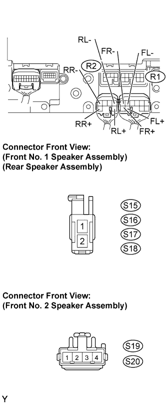 |
Disconnect the R2 and R1 radio receiver assembly connectors.
Disconnect the speaker connectors.
Check the resistance.
| Tester Connection | Specified Condition |
| FL+ (R1-2) - S19-4 | Below 1Ω |
| FL- (R1-6) - S19-3 | Below 1Ω |
| FR+ (R1-1) - S20-4 | Below 1Ω |
| FR- (R1-5) - S20-3 | Below 1Ω |
| S19-1 - S15-2 | Below 1Ω |
| S19-2 - S15-1 | Below 1Ω |
| S20-1 - S16-2 | Below 1Ω |
| S20-2 - S16-1 | Below 1Ω |
| RL+ (R2-2) - S17-1 | Below 1Ω |
| RL- (R2-6) - S17-2 | Below 1Ω |
| RR+ (R2-1) - S18-1 | Below 1Ω |
| RR- (R2-3) - S18-2 | Below 1Ω |
| FL+ (R1-2) - Body ground | 10 kΩ or higher |
| FL- (R1-6) - Body ground | 10 kΩ or higher |
| FR+ (R1-1) - Body ground | 10 kΩ or higher |
| FR- (R1-5) - Body ground | 10 kΩ or higher |
| RL+ (R2-2) - Body ground | 10 kΩ or higher |
| RL- (R2-6) - Body ground | 10 kΩ or higher |
| RR+ (R2-1) - Body ground | 10 kΩ or higher |
| RR- (R2-3) - Body ground | 10 kΩ or higher |
|
| ||||
| OK | |
|
| 3.INSPECT FRONT NO. 1 SPEAKER ASSEMBLY |
Measure the resistance between the terminals of the speaker.
|
| ||||
| OK | |
|
| 4.INSPECT FRONT NO. 2 SPEAKER ASSEMBLY |
Check that the malfunction disappears when another speaker in good condition is installed.
|
| ||||
| OK | |
|
| 5.INSPECT REAR SPEAKER ASSEMBLY |
Measure the resistance between the terminals of the speaker.
|
| ||||
| OK | ||
 | ||
| ||
| 6.CHECK HARNESS AND CONNECTOR (STEREO COMPONENT AMPLIFIER ASSEMBLY - SPEAKER ASSEMBLY) |
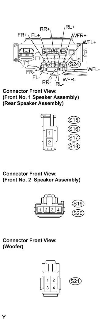 |
Disconnect the S24 connectors from the stereo component amplifier assembly and speakers.
Measure the resistance.
| Tester Connection | Specified Condition |
| FL+ (S24-6) - S19-4 | Below 1Ω |
| FL- (S24-17) - S19-3 | Below 1Ω |
| FR+ (S24-7) - S20-4 | Below 1Ω |
| FR- (S24-18) - S20-3 | Below 1Ω |
| S19-1 - S15-2 | Below 1Ω |
| S19-2 - S15-1 | Below 1Ω |
| S20-1 - S16-2 | Below 1Ω |
| S20-2 - S16-1 | Below 1Ω |
| RL+ (S24-4) - S17-1 | Below 1Ω |
| RL- (S24-13) - S17-2 | Below 1Ω |
| RR+ (S24-5) - S18-1 | Below 1Ω |
| RR- (S24-14) - S18-2 | Below 1Ω |
| FL+ (S24-6) - Body ground | 10 kΩ or higher |
| FL- (S24-17) - Body ground | 10 kΩ or higher |
| FR+ (S24-7) - Body ground | 10 kΩ or higher |
| FR- (S24-18) - Body ground | 10 kΩ or higher |
| RL+ (S24-4) - Body ground | 10 kΩ or higher |
| RL- (S24-12) - Body ground | 10 kΩ or higher |
| RR+ (S24-5) - Body ground | 10 kΩ or higher |
| RR- (S24-14) - Body ground | 10 kΩ or higher |
| WFL+ (S24-2) - Body ground | 10 kΩ or higher |
| WFL- (S24-11) - Body ground | 10 kΩ or higher |
| WFR+ (S24-3) - Body ground | 10 kΩ or higher |
| WFR- (S24-12) - Body ground | 10 kΩ or higher |
|
| ||||
| OK | |
|
| 7.INSPECT FRONT NO. 1 SPEAKER ASSEMBLY |
Measure the resistance between the terminals of the speaker.
|
| ||||
| OK | |
|
| 8.INSPECT FRONT NO. 2 SPEAKER ASSEMBLY |
Check that the malfunction disappears when another speaker in good condition is installed.
|
| ||||
| OK | |
|
| 9.INSPECT REAR SPEAKER ASSEMBLY |
Measure the resistance between the terminals of the speaker.
|
| ||||
| OK | |
|
| 10.INSPECT NO. 1 SPEAKER ASSEMBLY WITH BOX |
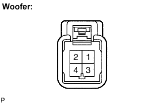 |
Measure the resistance.
| Tester Connection | Specified Condition |
| 1 - 3 | 2 Ω |
| 2 - 4 | 2 Ω |
|
| ||||
| OK | ||
| ||
| ||

