
POWER WINDOW CONTROL SYSTEM > TERMINALS OF ECU |
| CHECK POWER WINDOW REGULATOR MASTER SWITCH (FOR DOUBLE CAB): |
Disconnect the P9 power window regulator master switch connector.
Measure the voltage and resistance of each of the wire harness side connector terminals.
| Symbol (Terminal No.) | Wiring Color | Terminal Description | Condition | Specified Condition |
| E (P9-1) - Body ground | W-B - Body ground | Ground | Always | Below 1 Ω |
| B (P9-7) - E (P9-1) | R - W-B | Regulator motor power supply | Always | 10 to 14 V |
| B (P9-7) - E (P9-1) | R - W-B | Master switch power supply | Ignition switch OFF | 0 V |
| B (P9-7) - E (P9-1) | R - W-B | Master switch power supply | ignition switch ON | 10 to 14 V |
| DU (P9-4) - DD (P9-9) | L - L-B |
| Always | Below 1 Ω |
Reconnect the power window regulator master switch connector.
Measure the voltage of the connector terminals.
| Symbol (Terminal No.) | Wiring Color | Terminal Description | Condition | Specified Condition |
| DU (P9-4) - E (P9-1) | L - W-B | Power window motor UP output | Ignition switch ON, driver side power window switch OFF | 0 V |
| DU (P9-4) - E (P9-1) | L - W-B | Power window motor UP output | Ignition switch ON, driver side power window switch UP | 10 to 14 V |
| DD (P9-9) - E (P9-1) | L-B - W-B | Power window motor DOWN output | Ignition switch ON, driver side power window switch OFF | 0 V |
| DD (P9-9) - E (P9-1) | L-B - W-B | Power window motor DOWN output | Ignition switch ON, driver side power window switch DOWN (manual operation) | 10 to 14 V |
| DD (P9-9) - E (P9-1) | L-B - W-B | Power window motor DOWN output | Ignition switch ON, driver side power window fully closed → driver side power window switch DOWN (AUTO operation) → driver side power window fully open | 0 V → 10 to 14 V → 0 V |
Check the illumination.
When the ignition switch is turned to ON from OFF with the connector connected, check that the illumination (YELLOW) AUTO lights up.
| CHECK POWER WINDOW REGULATOR MASTER SWITCH (FOR ACCESS CAB): |

Disconnect the P9 power window regulator master switch connector.
Measure the voltage and resistance of each of the wire harness side connector terminals.
| Symbol (Terminal No.) | Wiring Color | Terminal Description | Condition | Specified Condition |
| E (P9-1) - Body ground | W-B - Body ground | Ground | Always | Below 1 Ω |
| B (P9-9) - E (P9-1) | R - W-B | Regulator motor power | Always | 10 to 14 V |
| B (P9-9) - E (P9-1) | R - W-B | Master switch power supply | Ignition switch OFF | 0 V |
| B (P9-9) - E (P9-1) | R - W-B | Master switch power supply | ignition switch ON | 10 to 14 V |
| DU (P9-3) - DD (P9-4) | L - L-B |
| Always | Below 1 Ω |
Reconnect the power window regulator master switch connector.
Measure the voltage of the connector terminals.
| Symbol (Terminal No.) | Wiring Color | Terminal Description | Condition | Specified Condition |
| DU (P9-4) - E (P9-1) | L - W-B | Power window motor UP output | Ignition switch ON, driver side power window switch OFF | 0 V |
| DU (P9-4) - E (P9-1) | L - W-B | Power window motor UP output | Ignition switch ON, driver side power window switch UP | 10 to 14 V |
| DD (P9-9) - E (P9-1) | L-B - W-B | Power window motor DOWN output | Ignition switch ON, driver side power window switch OFF | 0 V |
| DD (P9-9) - E (P9-1) | L-B - W-B | Power window motor DOWN output | Ignition switch ON, driver side power window switch DOWN (manual operation) | 10 to 14 V |
| DD (P9-9) - E (P9-1) | L-B - W-B | Power window motor DOWN output | Ignition switch ON, driver side power window fully closed → driver side power window switch DOWN (AUTO operation) → driver side power window fully open | 0 V → 10 to 14 V → 0 V |
Check the illumination.
When the ignition switch is turned to ON from OFF with the connector connected, check that the illumination (YELLOW) AUTO lights up.
| CHECK DRIVER SIDE J/B ASSEMBLY (MULTIPLEX NETWORK BODY ECU) |
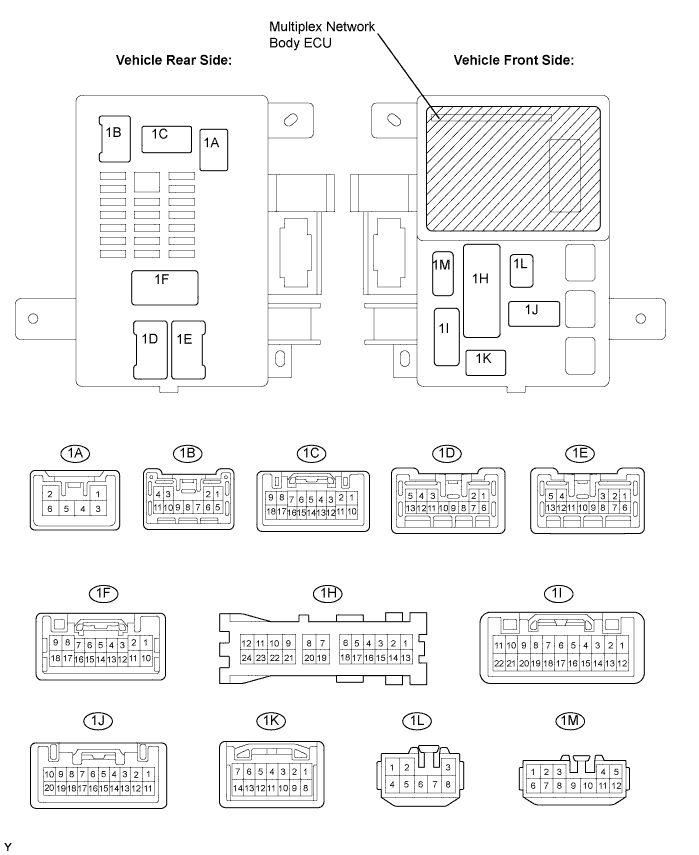
Disconnect the 1A, 1C, 1F, 1H, 1I and 1K driver side J/B connectors.
Measure the voltage and resistance between each terminal of the wire harness side connectors and body ground.
| Symbol (Terminal No.) | Wiring Color | Terminal Description | Condition | Specified Condition |
| ECUB (1C-16) - Body ground | R - Body ground | +B (ECUB) power supply | Always | 10 to 14 V |
| ALTB (1A-6) - Body ground | L - Body ground | +B (power system, generator system) power supply | Always | 10 to 14 V |
| PWS (1H-10) - Body ground | W-B - Body ground | PWR Relay ON signal | Ignition switch OFF | 0 V |
| Ignition switch ON | 10 to 14 V | |||
| KSW (1K-10) - Body ground | G-B - Body ground | Key unlock warning switch input | No key in ignition key cylinder | 10 kΩ or higher |
| Key inserted ignition key cylinder | Below 1 Ω | |||
| DCTY (1F-7) - Body ground | G-Y - Body ground | Driver side courtesy switch input | Driver side door CLOSED | 10 kΩ or higher |
| Driver side door OPEN | Below 1 Ω | |||
| PCTY (1I-8) - Body ground | R-B - Body ground | Passenger side courtesy switch input | Passenger side door CLOSED | 10 kΩ or higher |
| Passenger side door OPEN | Below 1 Ω | |||
| GND (1H-18) - Body ground | W-B - Body ground | Ground | Always | Below 1 Ω |
Reconnect the driver side J/B connectors.
Measure the voltage between each terminal of the connector and body ground.
| Symbol (Terminal No.) | Wiring Color | Terminal Description | Condition | Specified Condition |
| KSW (1K-10) - Body ground | G-B - Body ground | Key unlock warning switch input | No key in ignition key cylinder | 10 to 14 Vr |
| Key inserted ignition key cylinder | 0 V |