FUEL INJECTOR > INSTALLATION |
| 1. INSTALL FUEL INJECTOR |
|
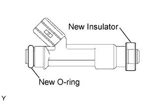
Install a new insulator onto each fuel injector.
Apply a light coat of spindle oil or gasoline to a new O-ring and install it onto each fuel injector.
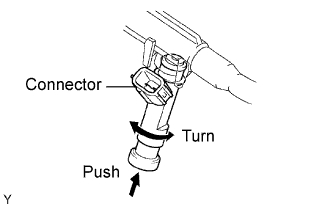 |
While turning the fuel injector left and right, install it onto the fuel delivery pipe.
Position the fuel injector connector facing outward.
| 2. INSTALL FUEL DELIVERY PIPE SUB-ASSEMBLY |
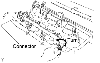 |
Place the fuel delivery pipe together with the 6 fuel injectors on the intake manifold.
Provisionally install the 6 bolts, which are used to hold the fuel delivery pipe, onto the intake manifold.
Check that the fuel injectors rotate smoothly.
Position the fuel injector connector facing outward.
Tighten the 6 bolts, which are used to hold the fuel delivery pipe, to the intake manifold.
Connect the 6 fuel injector connectors.
| 3. CONNECT FUEL PIPE SUB-ASSEMBLY |
Push the tube connector into the pipe until the tube connector makes a "click" sound.
Install the fuel pipe clamp.
| 4. CONNECT NO.1 FUEL PIPE SUB-ASSEMBLY |
Push the tube connector into the pipe until the tube connector makes a "click" sound.
Install the fuel pipe clamp.
| 5. INSTALL INTAKE AIR SURGE TANK |
Install a new gasket and the intake air surge tank with the 2 nuts.
Using an 8 mm socket hexagon wrench, install the 4 bolts.
Install the 3 upper bolts which are used to secure the 2 surge tank stays and throttle body bracket.
Install the 3 wire harness clamps and hose clamp.
Connect the throttle motor connector.
Connect the 2 VSV connectors.
Connect the ventilation hose.
Connect the fuel vapor feed hose.
Connect the water by-pass hose No. 4.
Connect the water by-pass hose No. 5.
| 6. INSTALL AIR CLEANER ASSEMBLY |
Install the air cleaner with the 2 bolts.
Connect the ventilation hose No. 2.
| 7. INSTALL V-BANK COVER |
Install the V-bank cover with the 2 nuts.
| 8. CONNECT CONNECT BATTERY NEGATIVE TERMINAL |
| 9. ADD ENGINE COOLANT |
Pour coolant into the radiator until it overflows.
| Transmission | Capacity |
| Manual Transmission | 9.7 liters (10.3 Us qts, 8.5 Imp. qts) |
| Automatic Transmission | 9.8 liters (10.4 Us qts, 8.6 Imp. qts) |
Check the coolant level inside the radiator by squeezing the inlet and outlet radiator hoses several times by hand. If the coolant level goes down, add coolant.
Install the radiator cap securely.
Slowly pour coolant into the radiator reservoir until it reaches the FULL line.
Warm up the engine until the cooling fan operates.
Set the air conditioning as follows while warming up the engine.
| Item | Condition |
| Fan Speed | Any setting except OFF |
| Temperature | Toward WARM |
| Air Conditioning Switch | OFF |
Maintain the engine speed at 2,000 to 2,500 rpm and warm up the engine until the cooling fan operates.
Squeeze the inlet and outlet radiator hoses several times by hand while warming up the engine.
Stop the engine and wait until the coolant cools down.
Remove the radiator cap and check the coolant level inside the radiator.
If the coolant level is below the full level, perform the steps from (a) through (h) and repeat the operation until the coolant level remains at the full level.
Check the coolant level inside the radiator reservoir tank again. If it is below the full level, add coolant.
| 10. CHECK FOR ENGINE COOLANT LEAKAGE |
Fill the radiator with coolant and attach a radiator cap tester.
Pump it to 118 kPa (1.2 kgf/cm2 17.1 psi), then check for leakage.
| 11. CHECK FOR FUEL LEAKAGE |