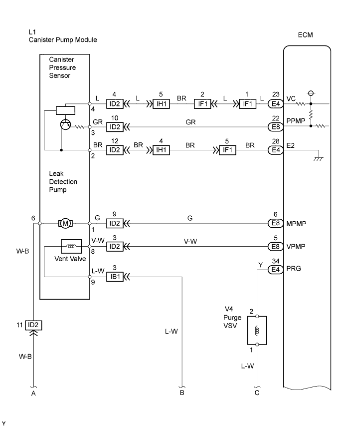
DTC P0450 Evaporative Emission Control System Pressure Sensor / Switch |
DTC P0451 Evaporative Emission Control System Pressure Sensor Range / Performance |
DTC P0452 Evaporative Emission Control System Pressure Sensor / Switch Low Input |
DTC P0453 Evaporative Emission Control System Pressure Sensor / Switch High Input |
| DTC | Monitoring Items | Malfunction Detection Conditions | Trouble Areas | Detection Timings | Detection logic |
| P0450 | Canister pressure sensor voltage abnormal fluctuation | Sensor output voltage rapidly fluctuates beyond upper and lower malfunction thresholds for 0.5 seconds. |
|
| 1 trip |
| P0451 | Canister pressure sensor noise | Sensor output voltage fluctuates frequently in certain time period. |
|
| 2 trip |
| Canister pressure sensor voltage fixed | Sensor output voltage does not vary in certain time period. |
|
| 2 trip | |
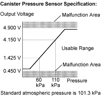
| P0452 | Canister pressure sensor voltage low | Sensor output voltage less than 0.45 V for 0.5 seconds. |
|
| 1 trip |
| P0453 | Canister pressure sensor voltage high | Sensor output voltage more than 4.9 V for 0.5 seconds. |
|
| 1 trip |
| Required Sensors/Components | Canister pump module |
| Frequency of Operation | Once per driving cycle: P0451 sensor stuck Continuous: P0451 sensor noise, P0450, P0452 and P0453 |
| Duration | - |
| MIL Operation | Immediate: P0450, P0452 and P0453 2 driving cycles: P0451 |
| Sequence of Operation | None |
| Monitor runs whenever these DTCs not present | None |
| Atmospheric pressure (absolute pressure) | 70 kPa (525 mmHg) or more, less than 110 kPa (825 mmHg) |
| Battery voltage | 10.5 V or more |
| Intake air temperature | 4.4° to 35°C (40° to 95°F) |
| Either of following conditions met | A or B |
| A. Engine | Running |
| B. Soak time (ignition switch OFF time) | 5 hours |
| First time | 7 hours |
| Second time | 9 hours and 30 minutes |
| Monitor runs whenever these DTCs not present | None |
| Atmospheric pressure | Less than 70 kPa (525 mmHg), or 110 kPa (825 mmHg) or more |
| Battery voltage | 10.5 V or more |
| Intake air temperature | 4.4° to 35°C (40° to 95°F) |
| Soak time (ignition switch OFF time) | 5 hours |
| First time | 7 hours |
| Second time | 9 hours and 30 minutes |
| Monitor runs whenever these DTCs not present | None |
| Either of following conditions met | (a) or (b) |
| (a) Ignition switch | ON |
| (b) Soak timer | ON |
| EVAP pressure | Less than 42.1 kPa (317 mmHg), or more than 123.8 kPa (928.5 mmHg) |
| Pressure variation indicated by canister pressure sensor in 10 seconds | More than +-0.3 kPa (+-2.25 mmHg) 10 times |
| 0.02 inch leak criterion variation indicated by canister pressure sensor in 10 seconds | Less than 0.65 kPa (4.87 mmHg) |
| EVAP pressure | Less than 42.1 kPa (317 mmHg) |
| EVAP pressure | More than 123.8 kPa (928.5 mmHg) |
| 1.CONFIRM DTC AND EVAP PRESSURE |
Connect an intelligent tester to the DLC3.
Turn the ignition switch ON (do not start the engine).
Turn the tester ON.
Select the following menu items: DIAGNOSIS / ENHANCED OBD II / DTC INFO / CURRENT CODES.
Read DTCs.
Select the following menu items: DIAGNOSIS / ENHANCED OBD II / DATA LIST / PRIMARY / VAPOR PRESS.
Read the EVAP (Evaporative Emission) pressure displayed on the tester.
| Display (DTC Output) | Test Results | Suspected Trouble Areas | Proceed to |
| P0451 | - |
| C |
| P0452 | Less than 45 kPa (430 mmHg) |
| A |
| P0453 | More than 120 kPa (900 mmHg) |
| B |
|
| ||||
|
| ||||
| A | |
 |
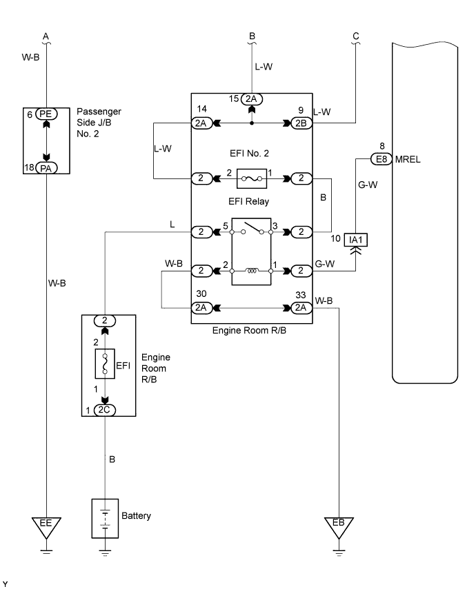
| 2.CHECK HARNESS AND CONNECTOR (CANISTER PUMP MODULE - ECM) |
 |
Turn the ignition switch OFF.
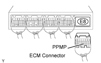
Disconnect the E8 ECM connector.
Measure the resistance between the PPMP terminal of the ECM connector and the body ground.
| Test Results | Suspected Trouble Areas | Proceed To |
| 10 Ω or less |
| A |
| 10 kΩ or more |
| B |
Reconnect the ECM connector.
|
| ||||
| A | |
|
| 3.CHECK HARNESS AND CONNECTOR (CANISTER PUMP MODULE - ECM) |
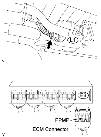 |
Disconnect the L1 canister connector.
Disconnect the E8 ECM connector.
Check the resistance between the PPMP terminal of the ECM connector and the body ground.
| Test Results | Suspected Trouble Areas | Proceed To |
| 10 kΩ or more |
| A |
| 10 Ω or less |
| B |
Reconnect the canister connector.
Reconnect the ECM connector.
|
| ||||
|
| ||||
| 4.CHECK HARNESS AND CONNECTOR (CANISTER PUMP MODULE - ECM) |
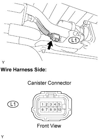 |
Disconnect the L1 canister connector.
Turn the ignition switch ON.
Measure the voltage and resistance of the L1 canister connector.
| Tester Connections | Specified Conditions |
| L1-4 - Body ground | Between 4.5 V and 5.5 V |
| L1-3 - Body ground | |
| L1-2 - Body ground | 100 Ω or less |
| Test Results | Suspected Trouble Areas | Proceed To |
| Voltage and resistance within standard ranges |
| A |
| Voltage and resistance outside standard ranges |
| B |
Reconnect the canister connector.
|
| ||||
|
| ||||
| 5.REPLACE CANISTER ASSEMBLY |
Replace the canister assembly (Click here).
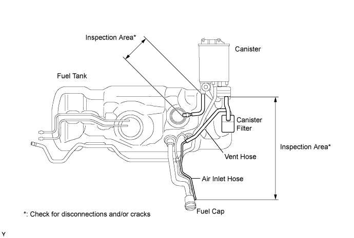
|
| ||||
| 6.REPAIR OR REPLACE HARNESS AND CONNECTOR |
|
| ||||
| 7.REPLACE ECM |
|
| ||||
| 8.CHECK WHETHER DTC OUTPUT RECURS (AFTER REPAIR) |
Connect an intelligent tester to the DLC3.
Turn the ignition switch ON and turn the tester ON.
Wait for at least 60 seconds.
Select the following menu items: DIAGNOSIS / ENHANCED OBD II / DTC INFO / PENDING CODES.
| NEXT | ||
 | ||
| ||

