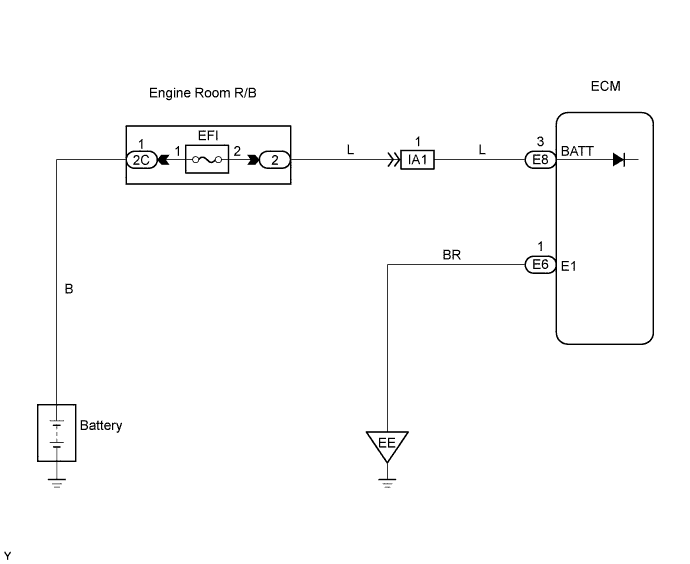
DTC P0560 System Voltage |
| DTC No. | DTC Detection Conditions | Trouble Areas |
| P0560 | Open in ECM back up power source circuit (1 trip detection logic) |
|
| Related DTCs | P0560: ECM system voltage |
| Required Sensors/Components (Main) | ECM |
| Required Sensors/Components (Related) | - |
| Frequency of Operation | Continuous |
| Duration | 3 seconds |
| MIL Operation | Immediate (MIL illuminated after next engine start) |
| Sequence of Operation | None |
| Monitor runs whenever following DTCs not present | None |
| Stand-by RAM | Initialized |
| ECM power source | Less than 3.5 V |
| 1.CHECK FUSE (EFI FUSE) |
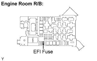 |
Remove the EFI fuse from the engine room R/B.
Check the resistance.
Reinstall the EFI fuse.
|
| ||||
| OK | |
 |
| 2.INSPECT ECM (BATT VOLTAGE) |
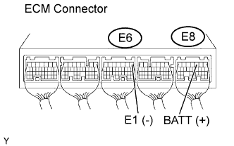 |
Measure the voltage between the terminals of the E8 and E6 ECM connectors.
| Tester Connections | Specified Conditions |
| BATT (E8-3) - E1 (E6-1) | 9 to 14 V |
|
| ||||
| OK | ||
 | ||
| ||
| 3.CHECK HARNESS AND CONNECTOR (ECM - EFI FUSE, EFI FUSE - BATTERY) |
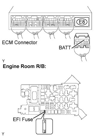 |
Check the harness and the connector between the EFI fuse and ECM.
Remove the EFI fuse from the engine room R/B.
Disconnect the E8 ECM connector.
Check the resistance.
| Tester Connections | Specified Conditions |
| EFI fuse (2) - BATT (E8-3) | Below 1 Ω |
| Tester Connections | Specified Conditions |
| EFI fuse (2) or BATT (E8-3) - Body ground | 10 kΩ or higher |
Reconnect the ECM connector.
Reinstall the EFI fuse.
Check the harness and the connector between the EFI fuse and battery.
Remove the EFI fuse from the engine room R/B.
Disconnect the positive battery terminal.
Check the resistance.
| Tester Connections | Specified Conditions |
| Battery positive terminal - EFI fuse (1) | Below 1 Ω |
| Tester Connections | Specified Conditions |
| Battery positive terminal or EFI fuse (1) - Body ground | 10 kΩ or higher |
Reconnect the positive battery terminal.
Reinstall the EFI fuse.
|
| ||||
| OK | |
|
| 4.INSPECT BATTERY |
Check that the battery is not depleted.
|
| ||||
| OK | ||
| ||
| ||

