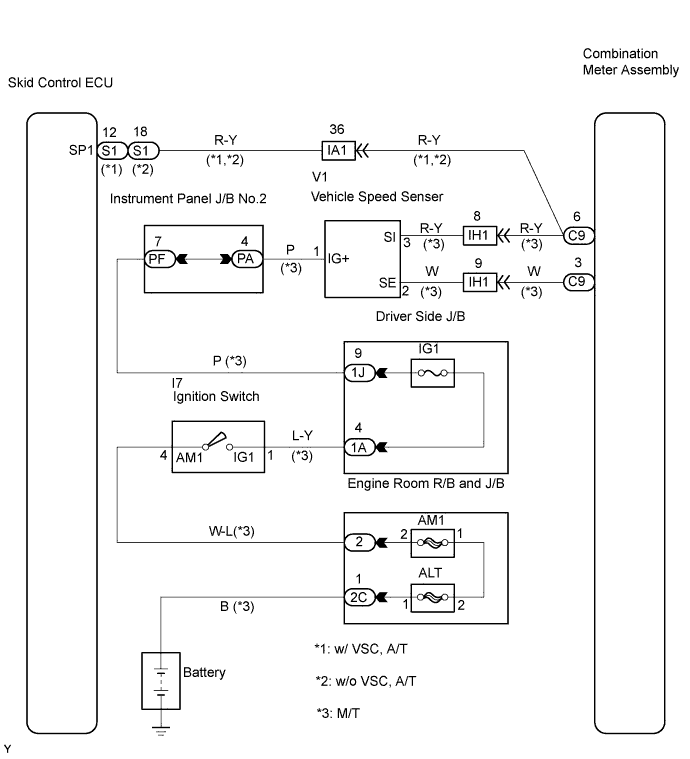
METER / GAUGE SYSTEM > Speedometer Malfunction |
| 1.READ VALUE OF INTELLIGENT TESTER (VEHICLE SPEED) |
Connect an intelligent tester to the DLC3.
Turn the ignition switch to ON.
Turn the tester ON.
On the tester, select the following menu items: DIAGNOSIS / ENHANCED OBD II / DATA LIST / ALL / VEHICLE SPD.
Read the value displayed on the tester.
|
| ||||
| OK | |
 |
| 2.INSPECT COMBINATION METER ASSEMBLY |
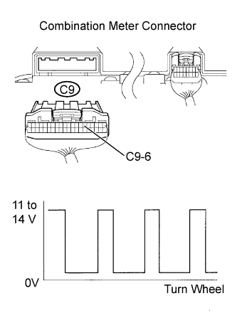 |
Shift the transmission gear selector lever to the neutral position.
Jack up the vehicle.
Turn the ignition switch to ON.
Check the voltage while the wheel is turning slowly.
| Tester Connection | Specified Condition |
| C9-6 - Body ground | Voltage generated intermittently |
| Result | Proceed to |
| As shown in the illustration | A |
| Different from the illustration (A/T) | B |
| Different from the illustration (M/T) | C |
|
| ||||
|
| ||||
| B | |
|
| 3.CHECK HARNESS AND CONNECTOR (SKID CONTROL ECU - COMBINATION METER ASSEMBLY) |
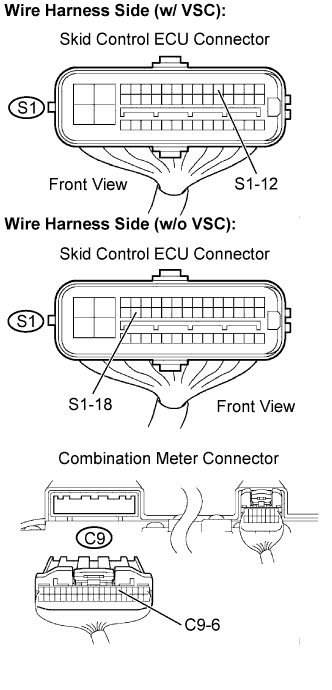 |
Disconnect the C9 combination meter connector.
With VSC: Disconnect the S1 skid control ECU connector.
Without VSC: Disconnect the S1 combination meter connector.
Measure the resistance.
| Tester Connection | Specified Condition |
| S1-12 - C9-6 | Below 1 Ω |
| S1-12 or C9-6 - Body ground | 10 kΩ or higher |
| Tester Connection | Specified Condition |
| S1-18 - C9-6 | Below 1 Ω |
| S1-18 or C9-6 - Body ground | 10 kΩ or higher |
Reconnect the skid control ECU connector.
Reconnect the combination meter connector.
|
| ||||
| OK | ||
 | ||
| ||
| 4.CHECK HARNESS AND CONNECTOR (VEHICLE SPEED SENSOR - COMBINATION METER ASSEMBLY) |
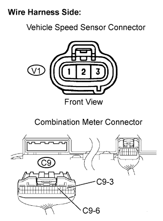 |
Disconnect the C9 combination meter connector.
Disconnect the V1 vehicle speed sensor connector.
Measure the resistance.
| Tester Connection | Specified Condition |
| C9-6 - V1-3 | Below 1 Ω |
| C9-3 - V1-2 | Below 1 Ω |
| C9-6 or V1-3 - Body ground | 10 kΩ or higher |
| C9-6 or V1-3 - Body ground | 10 kΩ or higher |
Measure the voltage.
| Tester Connection | Condition | Specified Condition |
| V1-1 - Body ground | Ignition switch OFF → ON | Below 1 V → 10 to 14 V |
Reconnect the vehicle speed sensor connector.
Reconnect the combination meter connector.
|
| ||||
| OK | ||
| ||
| ||

