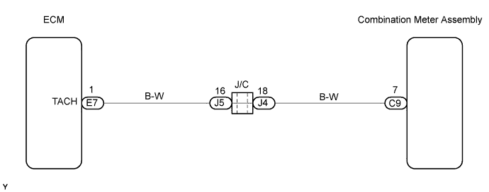
METER / GAUGE SYSTEM > Tachometer Malfunction |
| 1.READ VALUE OF INTELLIGENT TESTER (ENGINE SPEED) |
Connect an intelligent tester to the DLC3.
Turn the ignition switch to ON.
Turn the tester ON.
On the tester, select the following menu items: DIAGNOSIS / ENHANCED OBD II / DATA LIST / ALL / ENGINE SPD.
Read the value displayed on the tester.
|
| ||||
| OK | |
 |
| 2.INSPECT COMBINATION METER ASSEMBLY |
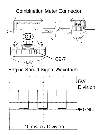 |
Inspect the combination meter using an oscilloscope.
While the engine is running, check the waveform between the terminals of the C9 combination meter connector and body ground.
| Tester Connection | Specified Condition |
| C9-7 - Body ground | Correct waveform shown |
|
| ||||
| NG | |
|
| 3.CHECK HARNESS AND CONNECTOR (COMBINATION METER ASSEMBLY - ECM) |
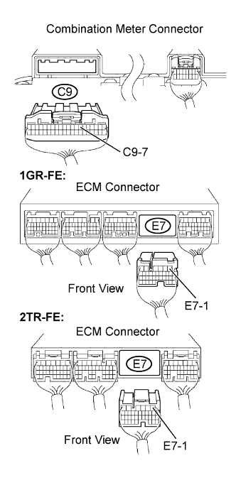 |
Disconnect the C9 combination meter connector.
Disconnect the E7 ECM connector.
Measure the resistance.
| Tester Connection | Specified Condition |
| C9-7 - E7-1 | Below 1 Ω |
| C9-7 or E7-1 - Body ground | 10 kΩ or higher |
Reconnect the ECM connector.
Reconnect the combination meter connector.
|
| ||||
| OK | ||
 | ||
| ||
