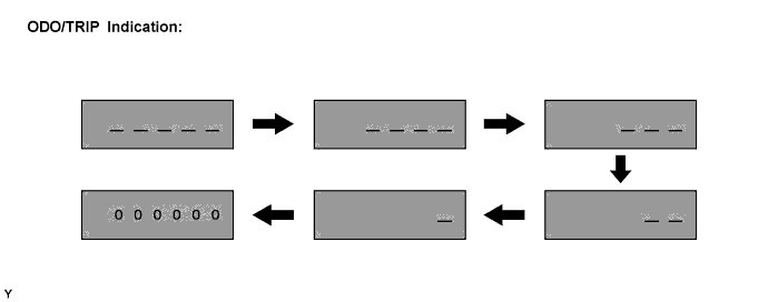
 |
Shift the transmission gear selector lever to the neutral position.
METER / GAUGE SYSTEM > ON-VEHICLE INSPECTION |
| 1. INSPECT SPEEDOMETER |
Check the operation.
Using a speedometer tester, inspect the speedometer for acceptable indication error and check the operation of the odometer.
| Standard Indication | Acceptable Range |
| 20 km/h | 17.5 to 21.5 km/h |
| 40 km/h | 38.0 to 42.0 km/h |
| 60 km/h | 58.0 to 63.0 km/h |
| 80 km/h | 78.0 to 84.0 km/h |
| 100 km/h | 98.5 to 104.5 km/h |
| 120 km/h | 119.0 to 125.0 km/h |
| 140 km/h | 139.0 to 146.0 km/h |
| 160 km/h | 159.0 to 167.0 km/h |
| 180 km/h | 179.0 to 188.0 km/h |
| 200 km/h | 199.0 to 209.0 km/h |
| 220 km/h | 219.0 to 230.0 km/h |
| 240 km/h | 239.0 to 251.0 km/h |
| Standard Indication | Acceptable Range |
| 20 mph | 20.0 to 23.0 mph |
| 40 mph | 40.0 to 43.5 mph |
| 60 mph | 60.0 to 64.0 mph |
| 80 mph | 80.0 to 84.5 mph |
| 100 mph | 100.0 to 105.0 mph |
| 120 mph | 120.0 to 125.5 mph |
| 140 mph | 140.0 to 146.0 mph |
Check the deflection width of the speedometer indicator.
| 2. INSPECT OUTPUT OF VEHICLE SPEED |
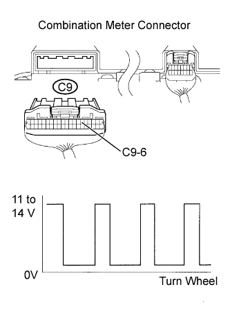
|
Shift the transmission gear selector lever to the neutral position.
Jack up the vehicle.
Turn the ignition switch to ON.
Check the voltage while the wheel is turning slowly.
| Tester Connections | Specified Conditions |
| C9-6 - Body ground | Voltage generated intermittently |
| 3. INSPECT TACHOMETER |
Check the operation.
Connect the tune-up test tachometer and start the engine.
Compare the result of the test with the standard indication.
| Standard Indication (USA) (RPM) Standard Indication (CANADA) (r/min) | 1GR-FE: Acceptable Range (USA) (RPM) Acceptable Range (CANADA) (r/min) Data in ( ) are for reference | 2TR-FE Acceptable Range (USA) (RPM) Acceptable Range (CANADA) (r/min) Data in ( ) are for reference |
| 700 | 630 to 770 | 630 to 770 |
| 1,000 | (900 to 1,100) | (900 to 1,100) |
| 2,000 | (1,850 to 2,150) | (1,850 to 2,150) |
| 3,000 | 2,800 to 3,200 | 2,800 to 3,200 |
| 4,000 | (3,800 to 4,200) | (3,800 to 4,200) |
| 5,000 | 4,800 to 5,100 | 4,800 to 5,200 |
| 6,000 | (5,750 to 6,250) | (5,750 to 6,250) |
| 4. INSPECT FUEL RECEIVER GAUGE |
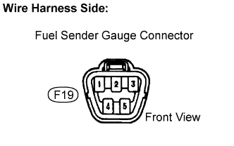 |
Disconnect the fuel sender gauge connector.
Turn the ignition switch to the ON position, then check the position of the receiver gauge needle.
Connect terminals 2 and 3 on the wire harness side connector of the fuel sender gauge.
Turn the ignition switch to the ON position, then check the position of the receiver gauge needle.
Reconnect the fuel sender gauge connector.
| 5. INSPECT FUEL LEVEL WARNING LIGHT |
Disconnect the fuel sender gauge connector.
Turn the ignition switch to the ON position, then check that the fuel level needle indicates EMPTY and the fuel level warning light comes on.
Reconnect the fuel sender gauge connector.
| 6. INSPECT LOW ENGINE OIL PRESSURE WARNING LIGHT |
Disconnect the low oil pressure switch connector.
Turn the ignition switch to the ON position.
Ground the terminal of the wire harness side connector, then check the low oil pressure warning light.
Reconnect the low oil pressure switch connector.
| 7. INSPECT BRAKE WARNING LIGHT |
Inspect the parking brake warning light.
Disconnect the parking brake switch connector.
Turn the ignition switch to the ON position.
Ground the terminal of the wire harness side connector, then check the parking brake warning light.
Reconnect the parking brake switch connector.
Inspect the brake fluid level warning light.
Disconnect the brake fluid level warning switch connector.
Turn the ignition switch to the ON position.
Connect a terminal to the other terminal of the wire harness side connector, then check the brake fluid level warning switch.
Reconnect the brake fluid level warning switch connector.
| 8. INSPECT BRAKE FLUID LEVEL WARNING SWITCH |
Remove the reservoir tank cap and strainer.
Disconnect the brake fluid level warning switch connector.
Measure the resistance between the terminals.
Use a syphon or a similar tool, to take fluid out of the reservoir tank.
Measure the resistance between the terminals.
Pour the fluid back in the reservoir tank.
Reconnect the brake fluid level warning switch connector.
Reinstall the reservoir tank cap and strainer.
| 9. INSPECT WASHER FLUID LEVEL WARNING SWITCH |
Disconnect the washer level warning switch connector.
Turn the ignition switch to the ON position.
Ground the terminal of the wire harness side connector, then check the washer level warning light.
Reconnect the washer level warning switch connector.
| 10. MAINTENANCE LIQUID RESETTING PROCEDURE |
| State | Condition | Specified State |
| Blinking | The vehicle has run 4,500 miles since the previous setting | The indicator blinks for 15 seconds after the ignition switch is turned to the ON position (including 3 seconds for a valve check). |
| Continuously Illuminated | The vehicle has run 5,000 miles since the previous setting | The indicator is continuously illuminated after the ignition switch is turned to the ON position. |
Turn the ignition switch to the ON position.
Set the ODO/TRIP indication to ODO.
While pressing the reset switch, turn the ignition switch OFF and ON again.
Press the reset switch for more than 5 seconds. (The oil maintenance indicator illuminates for 3 seconds, and then flashes in accordance with the distance run*.)