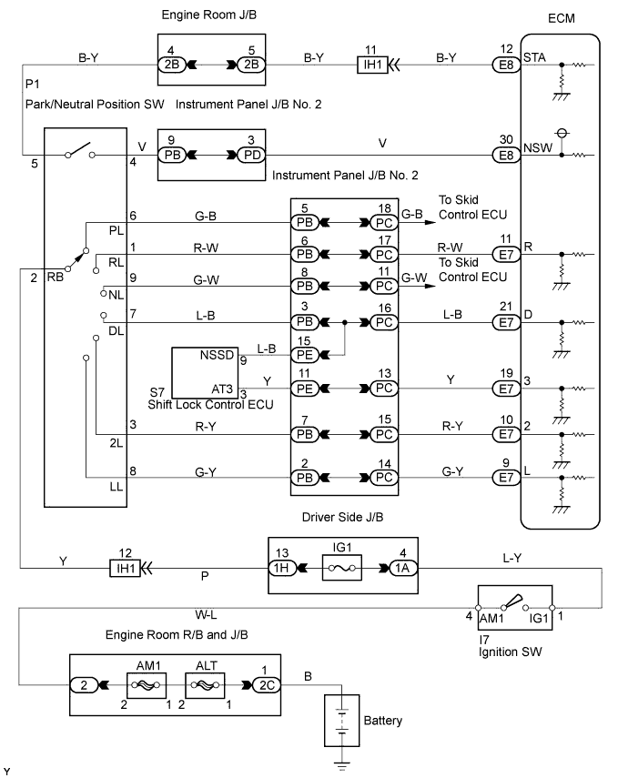
DTC P0705 Transmission Range Sensor Circuit Malfunction (PRNDL Input) |
DTC P0850 Park / Neutral Switch Input Circuit |
| DTC No. | DTC Detection Conditions | Trouble Areas |
| P0705 | Either of the following conditions is met: (a) Any 2 or more of the following signals are ON simultaneously. (2-trip detection logic)
|
|
| P0850 | Park/neutral position switch remains ON (P, N position) while driving under conditions (a) and (b) for 15 seconds. (2-trip detection logic) (a) Vehicle speed: 43.5 mph (70 km/h) or more (b) Engine speed: 1,500 to 2,500 rpm |
|
| Related DTCs | P0705: Park/neutral position switch/Verify switch input |
| Required sensors/Components | Park/neutral position switch |
| Frequency of operation | Continuous |
| Duration | 2 seconds |
| MIL operation | 2 driving cycles |
| Sequence of operation | None |
| Related DTCs | P0850: Park/Neutral position switch/Verify switch cycling |
| Required sensors/Components | Park/Neutral position switch |
| Frequency of operation | Continuous |
| Duration | 15 seconds |
| MIL operation | 2 driving cycles |
| Sequence of operation | None |
| The monitor will run whenever the following DTCs are not present. | None |
| Ignition switch | ON |
| Battery voltage | 10.5 V or more |
| The monitor will run whenever the following DTCs are not present. | None |
| Vehicle speed | 43.5 mph (70 km/h) or more |
| Engine speed | 1,500 rpm or more and 2,500 rpm or less |
| Intake air amount per revolution | 0.6 g/rev. or more |
| Number of the following signal input at the same time | 2 or more |
| Park/neutral position switch | ON |
| R switch | ON |
| D switch | ON |
| 2 switch | ON |
| Number of the following signal input at the same time | 2 or more |
| Park/neutral position switch | ON |
| R switch | ON |
| 3 switch | ON |
| L switch | ON |
| Park/neutral position switch | ON |
| Park/neutral position switch | The park/neutral position switch sends only one signal to the ECM. |
| Park/neutral position switch | The park/neutral position switch is OFF when vehicle speed is 43.5 mph (70 km/h) or more and engine speed is between 1,500 rpm and 2,500 rpm. |
| DATA LIST |
Connect the intelligent tester together with the CAN VIM (controller area network vehicle interface module) to the DLC3.
Turn the ignition switch to the ON position.
Push the "ON" button of the tester.
Select the items "DIAGNOSIS/ ENHANCED OBD II/ DATA LIST/ A/T".
According to the display on the tester, read the "DATA LIST".
| Item | Measurement Item/ Range (display) | Normal Condition | Diagnostic Note |
| PNP SW [NSW] | PNP SW Status/ ON or OFF | Shift lever position is; P or N: ON Except P and N: OFF | When the shift lever position displayed on the intelligent tester differs from the actual position, adjustment of the PNP switch or the shift cable may be incorrect. |
| REVERSE | PNP SW Status/ ON or OFF | Shift lever position is; R: ON Except R: OFF | |
| DRIVE | PNP SW Status/ ON or OFF | Shift lever position is; D: ON Except D: OFF | |
| 3RD | PNP SW Status/ ON or OFF | Shift lever position is; 3: ON Except 3: OFF | |
| 2ND | PNP SW Status/ ON or OFF | Shift lever position is; 2: ON Except 2: OFF | |
| LOW | PNP SW Status/ ON or OFF | Shift lever position is; L: ON Except L: OFF |
| 1.INSPECT SHIFT LOCK CONTROL ECU SUB-ASSEMBLY (TRANSMISSION CONTROL SWITCH) |
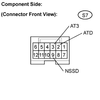 |
Disconnect the shift lock control ECU connector.
Measure the resistance when the shift lever is moved to each position.
| Shift Position | Tester Connection | Specified Condition |
| D | 9 (NSSD) - 2 (ATD) | Below 1 Ω |
| 3 | 9 (NSSD) - 2 (ATD) | 10 kΩ or higher |
| D | 9 (NSSD) - 3 (AT3) | 10 kΩ or higher |
| 3 | 9 (NSSD) - 3 (AT3) | Below 1 Ω |
|
| ||||
| OK | |
 |
| 2.INSPECT PARK/NEUTRAL POSITION SWITCH ASSEMBLY |
Connect the shift lock control ECM connector.
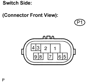 |
Disconnect the park/neutral position switch connector.
Measure the resistance when the shift lever is moved to each position.
| Shift Position | Tester Connection | Specified Condition |
| P | 2 - 6 and 4 - 5 | Below 1 Ω |
| Except P | 2 - 6 and 4 - 5 | 10 kΩ or higher |
| R | 1 - 2 | Below 1 Ω |
| Except R | 1 - 2 | 10 kΩ or higher |
| N | 2 - 9 and 4 - 5 | Below 1 Ω |
| Except N | 2 - 9 and 4 - 5 | 10 kΩ or higher |
| D, 3 | 2 - 7 | Below 1 Ω |
| Except D, 3 | 2 - 7 | 10 kΩ or higher |
| 2 | 2 - 3 | Below 1 Ω |
| Except 2 | 2 - 3 | 10 kΩ or higher |
| L | 2 - 8 | Below 1 Ω |
| Except L | 2 - 8 | 10 kΩ or higher |
|
| ||||
| OK | |
|
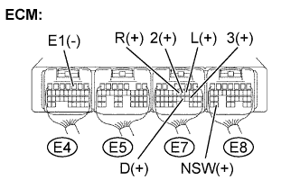
| 3.CHECK HARNESS AND CONNECTOR (PARK/NEUTRAL POSITION SWITCH - ECM) |
 |
Connect the park/neutral position switch connector.
Turn the ignition switch to the ON position.
Measure the voltage when the shift lever is moved to each position.
| Shift Position | Tester Connection | Specified Condition |
| P and N | E8-30 (NSW) - E4-3 (E1) | Below 1 V |
| Except P and N | E8-30 (NSW) - E4-3 (E1) | 10 to 14 V |
| R | E7-11 (R) - E4-3 (E1) | 10 to 14 V*
|
| Except R | E7-11 (R) - E4-3 (E1) | Below 1 V |
| D | E7-21 (D) - E4-3 (E1) | 10 to 14 V |
| Except D | E7-21 (D) - E4-3 (E1) | Below 1 V |
| 3 | E7-19 (3) - E4-3 (E1) | 10 to 14 V |
| Except 3 | E7-19 (3) - E4-3 (E1) | Below 1 V |
| 2 | E7-10 (2) - E4-3 (E1) | 10 to 14 V |
| Except 2 | E7-10 (2) - E4-3 (E1) | Below 1 V |
| L | E7-9 (L) - E4-3 (E1) | 10 to 14 V |
| Except L | E7-9 (L) - E4-3 (E1) | Below 1 V |
|
| ||||
| OK | ||
 | ||
| ||
