Home › TRANSMISSION · A340E AUTOMATIC TRANSMISSION › AUTOMATIC TRANSMISSION SYSTEM

DTC    P0710    Transmission Fluid Temperature Sensor "A" Circuit

DTC    P0712    Transmission Fluid Temperature Sensor "A" Circuit Low Input

DTC    P0713    Transmission Fluid Temperature Sensor "A" Circuit High Input

for Preparation Click here


DESCRIPTION

The ATF (Automatic Transmission Fluid) temperature sensor converts the fluid temperature into a resistance value which is input into the ECM. The No. 2 ATF temperature sensor is on the transmission and just before the oil cooler inlet pipeline.

HINT:
  1. The ATF temperature is liable to increase under conditions such as towing, climbing hills and in traffic.


The symptoms and recovery conditions, when the sensor is normal or there is a short malfunction in the sensor, are as shown in the table below. 
No. 2 ATF temperature sensor Status
Detection Condition
Symptom
Recovery Condition
Sensor is normal
  1. ATF temperature more than 130°C (266°F)
  1. Shift point too low
  1. ATF temperature less than 125°C (257°F)
Sensor is normal
When conditions (a) and (b) are satisfied continuously.
(a) ATF temperature more than 130°C (266°F)
(b) Engine coolant temperature more than 98°C (208.4°F)
  1. Lock-up in 4th or 3rd gear *1
  1. ATF temperature less than 110°C (230°F) and engine coolant temperature less than 98°C (208.4°F)
Sensor circuit is short
  1. Any conditions
  1. Shift point too low
  1. Symptom still occurs
Sensor circuit is short
  1. Engine coolant temperature more than 95°C (203°F)
  1. Lock-up in 4th or 3rd gear *1
  1. Symptom still occurs

HINT:
*1: When the ATF temperature is normal, the transmission locks up in 4th gear with the shift lever in the D position and in 3rd gear with the shift lever in the 3rd position.


DTC No.
DTC Detection Conditions
Trouble Areas
P0710
(a) and (b) are detected momentarily within 0.5 seconds when neither P0712 nor P0713 is detected. (1-trip detection logic)
(a) No. 2 ATF temperature sensor resistance is less than 79 Ω.
(b) No. 2 ATF temperature sensor resistance is more than 156 kΩ.

HINT:
Within 0.5 seconds the malfunction changes from (a) to (b) or from (b) to (a).

  1. Open or short in No. 2 ATF temperature sensor circuit
  2. No. 2 ATF temperature sensor
  3. ECM
P0712
No. 2 ATF temperature sensor resistance is less than 79 Ωfor 0.5 seconds or more. (1-trip detection logic)
  1. Short in No. 2 ATF temperature sensor circuit
  2. No. 2 ATF temperature sensor
  3. ECM
P0713
No. 2 ATF temperature sensor resistance is more than 156 kΩ for 0.5 seconds or more 15 minutes or more after starting engine. (1-trip detection logic)
  1. Open in No. 2 ATF temperature sensor circuit
  2. No. 2 ATF temperature sensor
  3. ECM

MONITOR DESCRIPTION

The Automatic Transmission Fluid (ATF) temperature sensor converts the ATF temperature to an electrical resistance value. Based on the resistance, the ECM determines the ATF temperature, and detects any open or short malfunctions in the AFT temperature circuit. If the resistance of the ATF temperature is less than 79 Ωor more than 156 kΩ, the ECM interprets this as a fault in the ATF temperature sensor or its wiring. The ECM turns on the MIL and stores a DTC.

MONITOR STRATEGY


Related DTCs
P0710: ATF temperature sensor/Range check (Fluttering)
P0712: ATF temperature sensor/Range check (Low resistance)
P0713: ATF temperature sensor/Range check (High resistance)
Required sensors/Components
ATF temperature sensor
Frequency of operation
Continuous
Duration
0.5 seconds
MIL operation
Immediate
Sequence of operation
None

TYPICAL ENABLING CONDITIONS


P0710: Range check (Fluttering) 
The monitor will run whenever the following DTCs are not present.
None
The typical enabling condition is not available.
-

P0712: Range check (Low resistance) 
The monitor will run whenever the following DTCs are not present.
None
The typical enabling condition is not available.
-

P0713: Range check (High resistance) 
The monitor will run whenever the following DTCs are not present.
None
Time after engine start
15 minutes or more

TYPICAL MALFUNCTION THRESHOLDS


P0710: Range check (Fluttering) 
TFT Sensor resistance
Less than 79 Ω
or
more than 156 kΩ

P0712: Range check (Low resistance) 
TFT Sensor resistance
Less than 79 Ω

P0713: Range check (High resistance) 
TFT Sensor resistance
More than 156 kΩ

COMPONENT OPERATING RANGE


ATF temperature sensor
Atmospheric temperature - approximately 130°C (266°F)

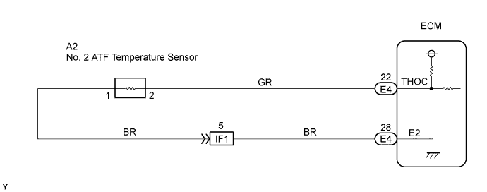
WIRING DIAGRAM


C121784E01


INSPECTION PROCEDURE


DATA LIST

HINT:
According to the DATA LIST displayed on the intelligent tester, you can read the values of components, such as the switches, sensors and actuators, without removing any parts. Reading the DATA LIST as the first step of troubleshooting is one method of shortening labor time.

NOTICE:
In the table below, the values listed under "Normal Condition" are for reference only. Do not depend solely on these reference values when judging whether a part is faulty or not.

  1. Warm up the engine.

  2. Turn the ignition switch off.

  3. Connect the intelligent tester together with the CAN VIM (controller area network vehicle interface module) to the DLC3.

  4. Turn the ignition switch to the ON position.

  5. Push the "ON" button of the tester.

  6. Select the items "DIAGNOSIS/ ENHANCED OBD II/ DATA LIST/ A/T".

  7. According to the display on the tester, read the "DATA LIST".

    Item
    Measurement Item/
    Range (display)
    Normal Condition
    A/T OIL TEMP3
    ATF Temperature Sensor Value/
    min.: -40°C (-40°F)
    max.: 215°C (419°F)
    1. After Stall Test;
      Approximately 80°C (176°F)
    2. Equal to ambient temperature when cold soak

    HINT:
    When DTC P0712 is output and the intelligent tester reading is 150°C (302°F) or more, there is an short circuit.
    When DTC P0713 is output and the intelligent tester reading is -40°C (-40°F), there is a open circuit.
    Measure the resistance between terminal THOC and the body ground.


    Temperature Displayed
    Malfunction
    -40°C (-40°F)
    Open circuit
    160 °C (320°F) or more
    Short circuit

    HINT:
    If a circuit related to the ATF temperature sensor becomes open, P0713 is immediately set (in 0.5 seconds).

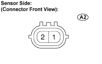
1.INSPECT TEMPERATURE SENSOR
A085194E02
  1. Disconnect the ATF temperature sensor connector from the transmission.

  1. Measure the resistance between the sensor connector terminals.

    Standard resistance:
    Tester Connection
    Specified Condition
    1 - 2
    79 Ω to 156 kΩ
    1 - Body ground
    10 kΩ or higher
    2 - Body ground
    10 kΩ or higher

    HINT:
    If the resistance is outside the specified range at either of the ATF temperatures shown in the table below, the driveability of the vehicle may decrease.

    ATF Temperature:
    Resistance:
    20 °C (68°F)
    10.3 to 13.9 kΩ
    110°C (230°F)
    0.68 to 0.88 kΩ


NG
REPAIR OR REPLACE TRANSMISSION WIRE
OK


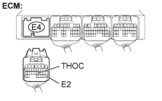
2.CHECK HARNESS AND CONNECTOR (ATF TEMPERATURE - ECM)
C095813E06
  1. Connect the transmission wire connector.

  1. Disconnect the ECM connector.

  1. Measure the resistance.

    Standard resistance:
    Tester Connection
    Specified Condition
    E4-22 (THOC) - E4-28 (E2)
    79 Ω to 156 kΩ
    E4-22 (THOC) - Body ground
    10 kΩ or higher
    E4-28 (E2) - Body ground
    10 kΩ or higher


NG
REPAIR OR REPLACE HARNESS OR CONNECTOR
OK

REPLACE ECM