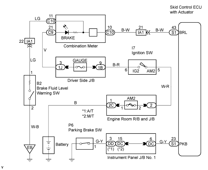
ANTI-LOCK BRAKE SYSTEM > Brake Warning Light Circuit |
| 1.CHECK BRAKE FLUID LEVEL |
Check the amount of brake fluid in the brake reservoir.
|
| ||||
| OK | |
 |
| 2.INSPECT BRAKE WARNING LIGHT |
When using intelligent tester:
Connect the intelligent tester to the DLC3.
Turn the ignition switch to the ON position.
Turn the intelligent tester ON.
Select the item "BRAKE WARN LIGHT" in the ACTIVE TEST and operate the BRAKE warning light on the intelligent tester.
| Item | Vehicle Condition / Test Details | Diagnostic Note |
| BRAKE WRN LIGHT | Turns BRAKE warning light ON / OFF | Observe combination meter |
Check that "ON" and "OFF" of the BRAKE warning light are indicated on the combination meter when using the intelligent tester.
When not using intelligent tester:
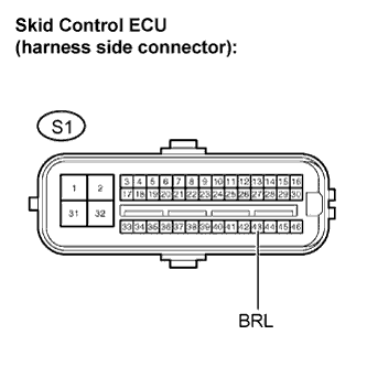 |
Disconnect the skid control ECU connector.
Turn the ignition switch to the ON position.
Ground terminal BRL of the skid control ECU.
Check the BRAKE warning light.
| BRL - GND Condition | Illumination Condition |
| Connecting | OFF |
| Disconnecting | ON |
Turn the ignition switch to OFF.
Reconnect the skid control ECU connector.
|
| ||||
| NG | |
|
| 3.INSPECT PARKING BRAKE SWITCH ASSEMBLY |
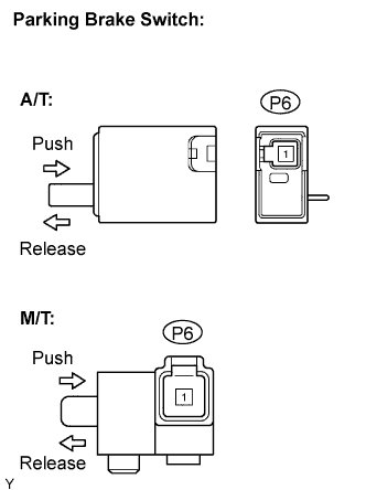 |
Disconnect the parking brake switch connector.
Measure the resistance.
| Tester Connection | Condition | Specified Condition |
| P6-1 Body ground | Released | Below 1 Ω |
| P6-1 Body ground | Pushed in | 10 kΩ or higher |
Reconnect the parking brake switch connector.
|
| ||||
| OK | |
|
| 4.CHECK HARNESS AND CONNECTOR (SKID CONTROL ECU - PARKING BRAKE SWITCH) |
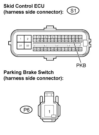 |
Disconnect the skid control ECU connector.
Disconnect the parking brake switch connector.
Measure the resistance.
| Tester Connection | Specified Condition |
| S1-23 (PKB) - P6-1 | Below 1 Ω |
| S1-23 (PKB) - Body ground | 10 kΩ or higher |
Reconnect the parking brake switch connector.
Reconnect the skid control ECU connector.
|
| ||||
| OK | |
|
| 5.INSPECT BRAKE FLUID LEVEL WARNING SWITCH CIRCUIT |
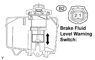 |
Disconnect the brake fluid level warning switch connector.
Measure the resistance.
| Tester Connection | Condition | Specified Condition |
| B2-1 - B2-2 | Float UP | 10 kΩ or higher |
| B2-1 - B2-2 | Float DOWN | Below 1 Ω |
Reconnect the brake fluid level warning switch connector.
|
| ||||
| OK | |
|
| 6.CHECK HARNESS AND CONNECTOR (COMBINATION METER - BRAKE FLUID LEVEL WARNING SWITCH) |
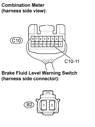 |
Disconnect the combination meter connector.
Disconnect the brake fluid level warning switch connector.
Measure the resistance.
| Tester Connection | Specified Condition |
| C10-11 - B2-1 | Below 1 Ω |
| C10-11 - Body ground | 10 kΩ or higher |
Reconnect the brake fluid level warning switch connector.
Reconnect the combination meter connector.
|
| ||||
| OK | |
|
| 7.INSPECT COMBINATION METER ASSEMBLY |
Check the combination meter system (Click here).
|
| ||||
| OK | ||
 | ||
| ||
