DTC P0340 Camshaft Position Sensor "A" Circuit (Bank 1 or Single Sensor) |
DTC P0342 Camshaft Position Sensor "A" Circuit Low Input (Bank 1 or Single Sensor) |
DTC P0343 Camshaft Position Sensor "A" Circuit High Input (Bank 1 or Single Sensor) |
DTC P0345 Camshaft Position Sensor "A" Circuit (Bank 2) |
DTC P0347 Camshaft Position Sensor "A" Circuit Low Input (Bank 2) |
DTC P0348 Camshaft Position Sensor "A" Circuit High Input (Bank 2) |
| DTC No. | DTC Detection Conditions | Trouble Areas |
| P0340 P0345 |
|
|
| P0342 P0347 | Output voltage of VVT sensor 0.3 V or less for 5 seconds (1 trip detection logic) | |
| P0343 P0348 | Output voltage of VVT sensor 4.7 V or more for 5 seconds (1 trip detection logic) |

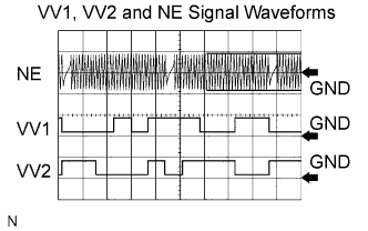
| Items | Contents |
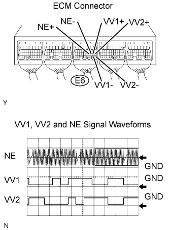
| Terminals | NE+ - NE- VV1+ - VV1- VV2+ - VV2- |
| Equipment Settings | 5V/Division, 20ms/Division |
| Conditions | Cranking or idling |
| Related DTCs | P0340: VVT sensor (Bank 1) open/short P0340: VVT position/Crankshaft position misalignment (Bank 1) P0342: VVT position sensor (Bank 1) range check (low voltage) P0343: VVT position sensor (Bank 1) range check (hign voltage) P0345: VVT sensor (Bank 2) open/short P0345: VVT position/Crankshaft position misalignment (Bank 2) P0347: VVT position sensor (Bank 2) range check (low voltage) P0348: VVT position sensor (Bank 2) range check (hign voltage) |
| Required Sensors/Components (Main) | VVT position sensors (Banks 1 and 2) |
| Required Sensors/Components (Related) | Crankshaft position sensor |
| Frequency of Operation | Continuous |
| Duration | 4 seconds: P0340 (Camshaft position sensor range check), P0345 (VVT sensor range check (While starting engine)) 5 seconds: Others |
| MIL Operation | 2 driving cycles: P0340 (Camshaft position sensor range check), P0345 (VVT sensor range check (While starting engine)) Immediate: Others |
| Sequence of Operation | None |
| Monitor runs whenever following DTCs not present | None |
| Starter | ON and not starter ON again |
| Minimum battery voltage while starter ON | Less than 11V |
| Engine RPM | 600 rpm or more |
| Starter | OFF |
| Starter | OFF |
| Ignition switch ON and time after ignition switch is OFF to ON | 2 seconds or more |
| Starter | ON |
| Battery voltage while starter ON once at least | Less than 11 V |
| Engine RPM | 600 rpm or more |
| Starter | OFF |
| Battery voltage | 8 V or more |
| Ignition switch | ON |
| Starter | OFF |
| Ignition switch ON and time after ignition switch is OFF to ON | 2 seconds or more |
| Battery voltage | 8 V or more |
| Camshaft position signal | No signal |
| Camshaft position and crankshaft position phase | Mis-aligned |
| Camshaft position position voltage | Less than 0.3 V, or more than 4.7 V |
| Camshaft position position voltage | Less than 0.3 V |
| Camshaft position position voltage | More than 4.7 V |
| VVT sensor signal | No signal |
| VVT sensor signal | No signal |
| VVT sensor voltage | Less than 0.3 V, or more than 4.7 V |
| VVT sensor voltage | Less than 0.3 V |
| VVT sensor voltage | More than 4.7 V |
| VVT sensor voltage | 0.3 to 4.7 V |
| 1.CHECK ECM TERMINAL VOLTAGE |
![]() |
Inspect the ECM using an oscilloscope.
While the engine is idling, check the waveform between the terminals of the ECM connector.
| Tester Connections | Specified Conditions |
| VV1+ (E6-19) - VV1- (E6-29) | Correct waveform as shown in illustration |
| VV2+ (E6-18) - VV2- (E6-28) | |
| NE+ (E6-21) - NE- (E6-20) |
|
| ||||
| OK | |
| 2.CHECK VVT SENSOR (SENSOR POWER SOURCE) |
![]() |
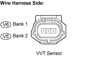
Disconnect the V6 or V5 VVT sensor connector.
Measure the voltage between the terminals of the VVT sensor.
| Tester Connection | Specified Condition |
| 3 - Body ground | 4.5 to 5.0 V |
Reconnect the VVT sensor connector.
|
| ||||
| OK | |
| 3.CHECK HARNESS AND CONNECTOR (VVT SENSOR - ECM) |
![]() |
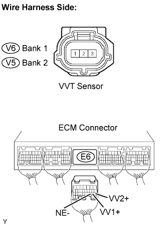
Disconnect the V5 or V6 VVT sensor connector.
Disconnect the E6 ECM connector.
Check the resistance.
| Tester Connections | Specified Conditions |
| VVT sensor (V6-1) - VV1+ (E6-19) | Below 1 Ω |
| VVT sensor (V5-1) - VV2+ (E6-18) | |
| VVT sensor (V6-2) - VV1- (E6-29) | |
| VVT sensor (V5-2) - VV2- (E6-28) |
| Tester Connections | Specified Conditions |
| VVT sensor (V6-1) or VV1+ (E6-19) - Body ground | 10 kΩ or higher |
| VVT sensor (V5-1) or VV2+ (E6-18) - Body ground | |
| VVT sensor (V6-2) or VV1- (E6-29) - Body ground | |
| VVT sensor (V5-2) or VV2- (E6-28) - Body ground |
Reconnect the VVT sensor connector.
Reconnect the ECM connector.
|
| ||||
| OK | |
| 4.CHECK SENSOR INSTALLATION (VVT SENSOR) |
|
| ||||
| OK | |
| 5.CHECK CAMSHAFT TIMING GEAR ASSEMBLY (TEETH PLATE) |
Check the teeth of the signal plate.
|
| ||||
| OK | ||
| ||