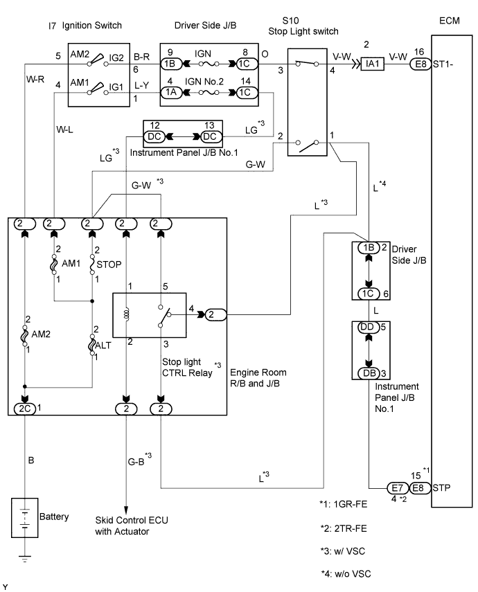
DTC P0571 Stop Light Switch Circuit Malfunction |
| DTC No. | DTC Detected Conditions | Trouble Areas |
| P0571 | ECM detects a malfunction of the stop light switch circuit under both of the following conditions.
|
|
| 1.INSPECT STOP LIGHT SWITCH OPERATION (FOR STOP LIGHT) |
Check that the stop lights come on while the brake pedal is depressed, and go off when the brake pedal is released.
| Brake pedal condition | Stop light condition |
| Depressed | ON |
| Released | OFF |
|
| ||||
| OK | |
 |
| 2.INSPECT STOP LIGHT SWITCH OPERATION (FOR BACK-UP SIGNAL) |
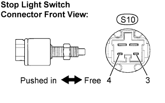 |
Turn the ignition switch off.
Disconnect the stop light switch assembly connector.
Measure the resistance according to the value(s) in the table below.
| Tester connection | Switch condition | Stop light condition |
| S10-3 - S10-4 | Switch pin free (Brake pedal depressed) | 10 kΩ or higher |
| S10-3 - S10-4 | Switch pin pushed in (Brake pedal released) | Below 1Ω |
Reconnect the stop light switch assembly connector.
|
| ||||
| OK | |
|
| 3.INSPECT ECM (STP SIGNAL) |
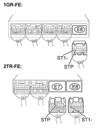 |
Reconnect the stop light switch assembly connector.
1GR-FE: Disconnect the E8 ECM connector.
2TR-FE: Disconnect the E7 and E8 ECM connectors.
Turn the ignition switch to the ON position.
Measure the voltage according to the value(s) in the table below.
| Tester connection | Brake pedal condition | Specification |
| STP (E8-15) - Body ground | Depressed | 10 to 14 V |
| STP (E8-15) - Body ground | Released | Below 1V |
| Tester connection | Brake pedal condition | Specification |
| STP (E7-4) - Body ground | Depressed | 10 to 14 V |
| STP (E7-4) - Body ground | Released | Below 1V |
Measure the voltage according to the value(s) in the table below.
| Tester connection | Brake pedal condition | Specification |
| ST1 (E8-16) - Body ground | Depressed | Below 1V |
| ST1 (E8-16) - Body ground | Released | 10 to 14 V |
| Tester connection | Brake pedal condition | Specification |
| ST1 (E8-16) - Body ground | Depressed | Below 1V |
| STP (E8-16) - Body ground | Released | 10 to 14 V |
Reconnect the ECM connector.
|
| ||||
| OK | ||
 | ||
| ||
