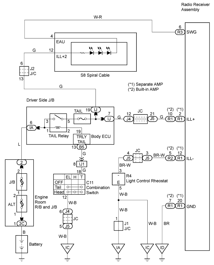
AUDIO AND VISUAL SYSTEM > Illumination Circuit |
| 1.SYSTEM CHECK |
Turn the light control switch to the TAIL or HEAD position.
Check whether other displays and indicators such as the A/C switch indicator come on.
|
| ||||
| OK | |
 |
| 2.CHECK SYMPTOMS |
Check the symptom.
Check whether the illumination for the radio receiver assembly or steering pad switch comes on.
| Symptom | Proceed To |
| Illumination for radio receiver assembly does not come on. | A |
| Illumination for steering pad switch does not come on. | B |
|
| ||||
| A | |
|
| 3.CHECK RADIO RECEIVER ASSEMBLY |
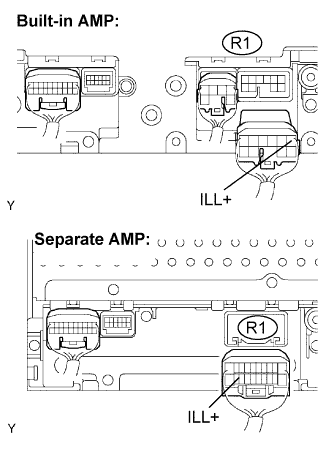 |
Disconnect the R1 radio receiver assembly connector.
Turn the light control switch to the TAIL or HEAD position.
Measure the voltage.
| Tester Connection | Light control switch TAIL | Specified Condition |
| ILL+ (R1-10) - Body ground | Light control switch TAIL | 10 to 14 V |
| Tester Connection | Light control switch TAIL | Specified Condition |
| ILL+ (R1-2) - Body ground | Light control switch TAIL | 10 to 14 V |
|
| ||||
| OK | |
|
| 4.CHECK HARNESS AND CONNECTOR (RADIO RECEIVER ASSEMBLY - LIGHT CONTROL RHEOSTAT) |
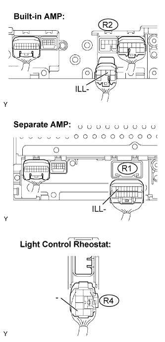 |
Disconnect the R2 or R1 radio receiver assembly connector and R4 light control rheostat connector.
Measure the resistance.
| Tester Connection | Specified Condition |
| ILL- (R2-5) - - (R4-3) | Below 1Ω |
| ILL- (R2-5) - Body ground | 10 kΩ or higher |
| Tester Connection | Specified Condition |
| ILL- (R1-12) - - (R4-3) | Below 1Ω |
| ILL- (R1-2) - Body ground | 10 kΩ or higher |
|
| ||||
| OK | ||
 | ||
| ||
| 5.INSPECT STEERING PAD SWITCH LH |
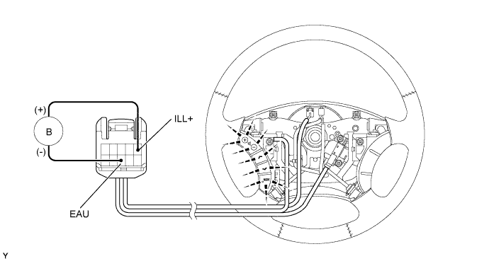
Disconnect the steering pad switch assembly connector.
Connect the positive (+) lead to terminal ILL+ and the negative (-) lead to terminal EAU of the steering pad switch assembly connector.
Check the illumination for the steering pad switch assembly.
|
| ||||
| OK | |
|
| 6.CHECK HARNESS AND CONNECTOR (SPIRAL CABLE SUB-ASSEMBLY - RADIO RECEIVER ASSEMBLY) |
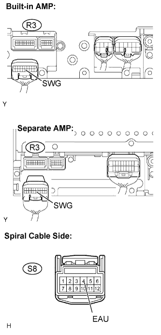 |
Disconnect the R3 radio receiver assembly connector.
Disconnect the S8 spiral cable sub-assembly connector.
Measure the resistance.
| Tester Connection | Specified Condition |
| SWG (R3-6) - EAU (S8-4) | Below 1 Ω |
|
| ||||
| OK | |
|
| 7.INSPECT SPIRAL CABLE SUB-ASSEMBLY |
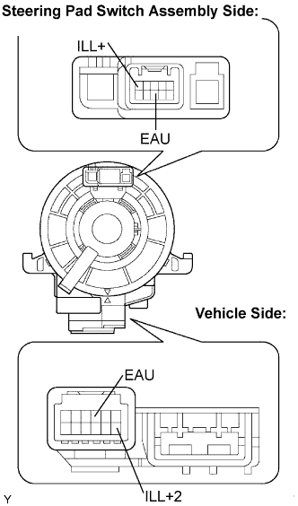 |
Disconnect the spiral cable sub-assembly connector.
Check the resistance.
| Tester Connection | Specified Condition |
| EAU - EAU | Below 1 Ω |
| ILL+ - ILL+2 | Below 1 Ω |
|
| ||||
| OK | ||
| ||
| ||

