AIR CONDITIONING CONTROL ASSEMBLY > INSPECTION |
| 1. INSPECT AIR CONDITIONING CONTROL ASSEMBLY |
![]() |
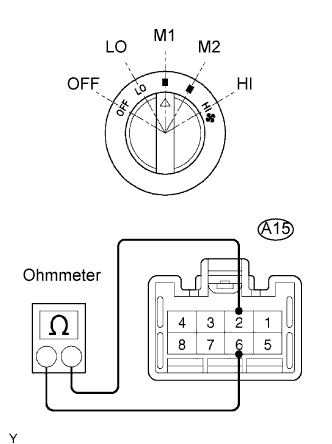
Check the blower switch resistance.
Using an ohmmeter, measure the resistance and check the results in accordance with the values in the table below.
| Tester connection | Blower Switch Position | Specified Condition |
| 2 - 3 - 4 - 6 - 7 | OFF | 10 KΩ or higher |
| 2 - 6 | LO | Below 1 Ω |
| 2 - 6 - 7 | LO - M1 | Below 1 Ω |
| 2 - 6 - 7 | M1 | Below 1 Ω |
| 2 - 4 - 6 - 7 | M1 - M2 | Below 1 Ω |
| 2 - 4 - 6 | M2 | Below 1 Ω |
| 2 - 3 - 4 - 6 | M2 - HI | Below 1 Ω |
| 2 - 3 - 6 | HI | Below 1 Ω |
![]() |
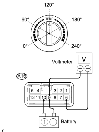
Check the temperature selector switch voltage.
Apply battery voltage (13.5V) across terminals 10 (IG) and 9 (GND).
Connect the positive (+) tester probe of a voltmeter to terminal 6 (AMSW) and the negative (-) tester probe to terminal 9 (GND), then check the voltage.
| Angle (Position) | Specified Condition |
| 0° (MAX COOL) | 13.0 to 13.5 V |
| 60° (COOL) | 9.7 to 10.6 V |
| 120° | 6.3 to 7.2 V |
| 180° (HOT) | 2.9 to 3.8 V |
| 240° (MAX HOT) | 0 to 0.5 V |
![]() |
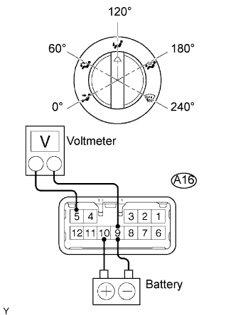
Check the mode selector switch voltage.
Apply battery voltage (13.5V) across terminals 10 (IG) and 9 (GND).
Connect the positive (+) tester probe of a voltmeter to terminal 5 (MSET) and the negative (-) tester probe to terminal 9 (GND), then check the voltage.
| Angle (Position) | Specified Condition |
| 0° (FACE) | 13.3 to 13.5 V |
| 60° (B/L) | 10.1 to 11.0 V |
| 120° (FOOT) | 6.3 to 7.2 V |
| 180° (FOOT/DEF) | 2.7 to 3.4 V |
| 240° (DEF) | 0 to 0.2 V |
![]() |
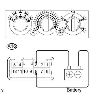
Inspect the illumination operation.
Connect the positive (+) lead from the battery to terminal 3 (ILL+) and negative (-) lead to terminal 8 (ILL-), then check that the illuminations light up.
![]() |
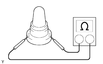
Inspect the bulb.
Inspect continuity of the bulb by connecting the tester as shown in the illustration.
![]() |
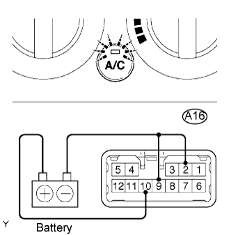
Inspect A/C indicator operation.
Connect the positive (+) lead from the battery to terminal 10 (IG) and negative (-) lead to terminal 2 (ACID) and 9 (GND).
Push the A/C button in and then check that the indicator lights up.
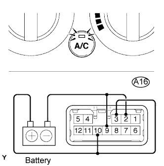
![]() |
Under the above condition, connect the positive (+) lead from the battery to terminal 3 (ILL+) and then check that the indicator dims.
![]() |
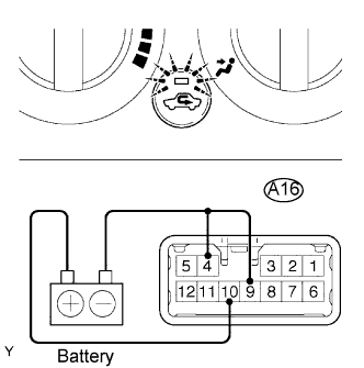
Inspect the REC indicator operation.
Connect the positive (+) lead from the battery to terminal 10 (IG) and negative (-) lead to terminal 4 (REC) and 9 (GND).
Push the REC button in and then check that the indicator lights up.
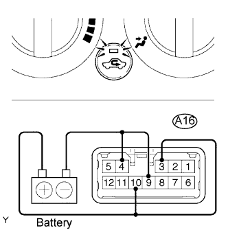
![]() |
Under the above condition, connect the positive (+) lead from the battery to terminal 3 (ILL+) and then check that the indicator dims.