Home › HEATER & AIR CONDITIONING SYSTEM › AIR CONDITIONING › SERVO MOTOR

SERVO MOTOR > INSPECTION

for Preparation Click here


1. INSPECT AIR INLET CONTROL SERVO MOTOR


    I045068E01
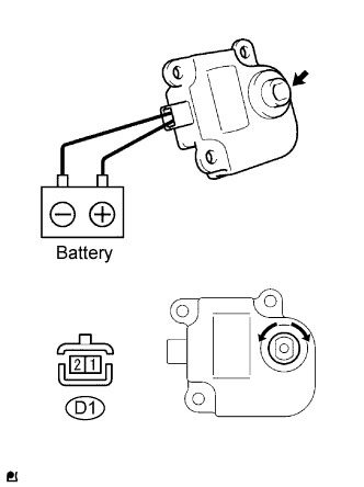
  1. Inspect the servo motor operation.

    1. Connect the positive (+) lead from the battery to terminal 1 (FRS) and negative (-) lead to terminals 2 (REC), then check that the shaft rotates clockwise smoothly.

    2. Connect the positive (+) lead from the battery to terminal 2 (REC) and negative (-) lead to terminal 1 (FRS) then check that the shaft rotates counter clockwise smoothly.
      If the operations are not as specified, replace the air control servo motor.


2. INSPECT MODE CONTROL SERVO MOTOR


    I045423E01
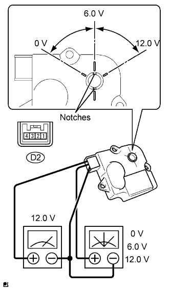
  1. Inspect the servo motor operation.

    1. When 12V is applied between terminals 4 (IGN) and 1 (GND), and 0V is applied between terminals 2 (SIG) and 1 (GND), check that the line connecting the 2 notches moves to the 0V position.
      If the result is not as specified, replace the mode control servo motor.

    2. When 12V is applied between terminals 4 (IGN) and 1 (GND), and 6V is applied between terminals 2 (SIG) and 1 (GND), check that the line connecting the 2 notches moves to the 6V position.
      If the result is not as specified, replace the mode control servo motor.

    3. When 12V is applied between terminals 4 (IGN) and 1 (GND), and between terminals 2 (SIG) and 1 (GND), check that the line connecting the 2 notches moves to the 12V position.
      If the result is not as specified, replace the mode control servo motor.


3. INSPECT AIR MIX CONTROL SERVO MOTOR


    I045423E02
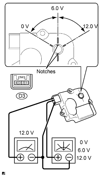
  1. Inspect the servo motor operation.

    1. When 12 V is applied between terminals 4 (IGN) and 1 (GND), and 0V is applied between terminals 2 (SIG) and 1 (GND), check that the line connecting the 2 notches moves to the 0V position.
      If the result is not as specified, replace the air mix control servo motor.

    2. When 12V is applied between terminals 4 (IGN) and 1 (GND), and 6V is applied between terminals 2 (SIG) and 1 (GND), check that the line connecting the 2 notches moves to the 6V position.
      If the result is not as specified, replace the air mix control servo motor.

    3. When 12V is applied between terminals 4 (IGN) and 1 (GND), and between terminals 2 (SIG) and 1 (GND), check that the line connecting the 2 notches moves to the 12V position.
      If the result is not as specified, replace the air mix control servo motor.