REAR DIFFERENTIAL CARRIER ASSEMBLY > REASSEMBLY |
| 1. INSTALL DIFFERENTIAL CASE ASSEMBLY |
|
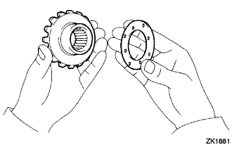
Install the rear differential side gear thrust washer onto the rear differential side gear.
Install the rear differential pinion thrust washer and rear differential pinion onto the rear differential spider.
Fix the differential case RH.
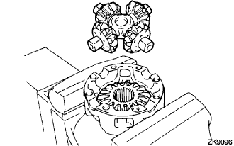 |
Install the rear differential side gear and rear differential spider onto the differential case RH.
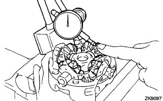 |
Using a dial indicator, measure the differential case RH side backlash while holding the pinion toward the case.
Remove the rear differential spider from the differential case RH.
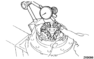 |
Install the rear differential side gear and rear differential spider onto the differential case LH.
Using a dial indicator, measure the differential case LH side backlash while holding the pinion toward the case.
| Thickness mm (in.) | Thickness mm (in.) |
| 0.9 (0.0354) | 1.2 (0.0472) |
| 1.0 (0.0394) | 1.3 (0.0512) |
| 1.1 (0.0433) | - |
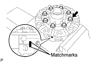 |
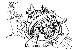
Align the matchmarks and assemble the RH and LH cases.
Using a plastic hammer, install the differential case.
Install the 8 bolts.
| 2. INSTALL DIFFERENTIAL RING GEAR |
 |
Clean the contact surfaces of the differential case and ring gear.
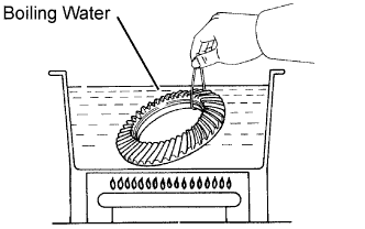
Heat the ring gear to approximately 100°C (212°F) in boiling water.
Carefully take the ring gear out of the boiling water.
After the moisture on the ring gear has completely evaporated, quickly install the ring gear onto the differential case.
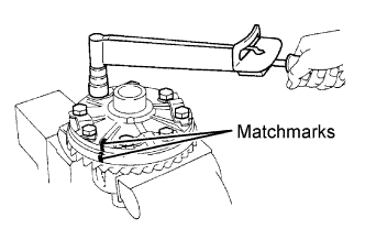 |
Align the matchmarks on the ring gear and differential case.
Temporarily install 5 new lock plates and 10 bolts.
After the ring gear cools down sufficiently, torque the 8 bolts uniformly.
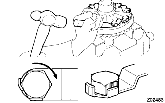 |
Using a chisel and a hammer, stake the 5 lock plates.
| 3. INSTALL REAR DIFFERENTIAL CASE BEARING |
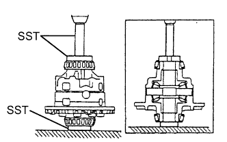 |
Using SST and a press, install the bearing onto the differential case.
| 4. INSPECT DIFFERENTIAL RING GEAR RUNOUT |
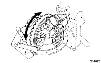 |
Install the differential case onto the carrier, and install the 2 adjusting nuts so that there is no play in the bearing.
Install the 2 bearing caps with the 4 bolts.
Using a dial indicator, measure the runout of the ring gear.
Remove the 2 bearing caps, 2 adjusting nuts and differential case.
| 5. INSTALL REAR DIFFERENTIAL DUST DEFLECTOR |
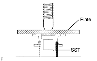 |
Using a press, install the dust deflector.
| 6. INSTALL REAR DRIVE PINION FRONT TAPERED ROLLER BEARING |
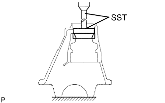 |
Using a brass bar and a hammer, install the oil storage ring.
Using SST and a press, install the tapered roller bearing onto the carrier.
| 7. INSTALL REAR DRIVE PINION REAR TAPERED ROLLER BEARING |
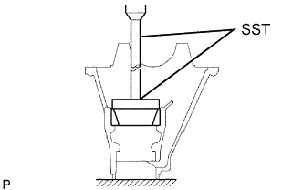 |
Using SST and a press, install the tapered roller bearing onto the carrier.
| 8. INSTALL REAR DRIVE PINION REAR TAPERED ROLLER BEARING |
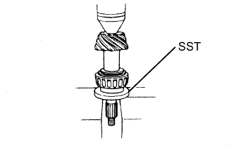 |
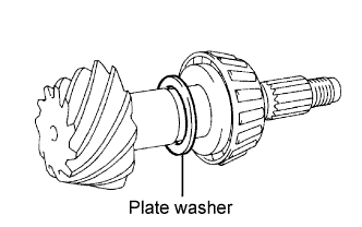
Install the plate washer onto the drive pinion.
Using SST and a press, install the tapered roller bearing onto the drive pinion.
| 9. ADJUST DIFFERENTIAL DRIVE PINION PRELOAD |
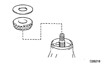 |
Install the drive pinion, rear drive pinion tapered roller bearing and rear differential drive oil slinger.
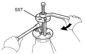 |
Using SST, install the drive pinion companion flange.
Coat the threads of the nut with hypoid gear oil LSD.
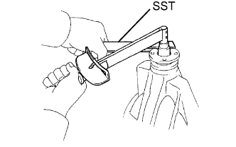 |
Using SST to hold the drive pinion companion flange, tighten the nut.
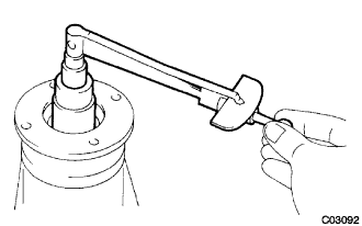 |
Using a torque wrench, measure the preload.
| Bearing | Standard |
| New | 1.05 to 1.64 N*m (10.7 to 16.7 kgf*cm, 9.3 to 14.5 in.*lbf) |
| Reused | 0.56 to 0.85 N*m (5.7 to 8.7 kgf*cm, 4.9 to 7.5 in.*lbf) |
| 10. INSTALL DIFFERENTIAL CASE ASSEMBLY |
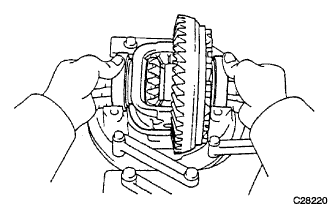 |
Place the 2 bearing outer races on their corresponding bearings.
| 11. INSTALL REAR DIFFERENTIAL BEARING ADJUSTING NUT |
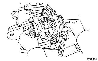 |
Install the 2 adjusting nuts into the carrier, making sure the nuts are threaded properly.
| 12. INSPECT AND ADJUST BACKLASH DIFFERENTIAL RING GEAR AND DIFFERENTIAL DRIVE PINION |
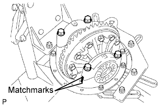 |
Align the matchmarks on the cap and carrier.
Install the right and left bearing caps with the 4 bolts.
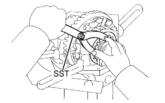 |
Tighten the 4 bearing cap bolts to the specified torque, then loosen them to the point where the adjusting nuts can be turned by SST.
Using the SST, tighten the adjusting nut on the ring gear side until the ring has a backlash of about 0.2 mm (0.008 in.).
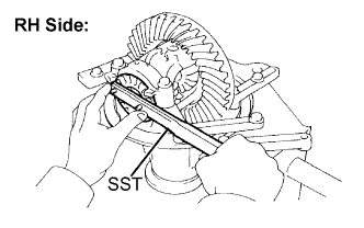 |
While turning the ring gear, use the SST to fully tighten the adjusting nut on the drive pinion side.
After the bearings have settled, loosen the adjusting nut on the drive pinion side.
Using SST, torque the adjusting nut 1 to 1.5 notches from the 0 preload position.
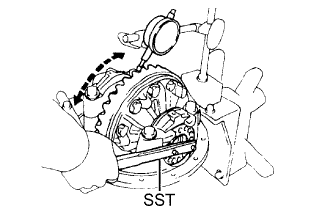 |
Using a dial indicator, adjust the ring gear backlash until it is within the specification.
 |
Torque the bearing cap bolts.
| 13. INSPECT TOTAL PRELOAD |
|
Using a torque wrench, measure the preload with the teeth of the drive pinion and ring gear in contact.
| 14. INSPECT TOOTH CONTACT BETWEEN RING GEAR AND DRIVE PINION |
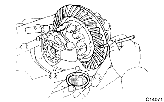 |
Coat 3 or 4 teeth at 3 different positions on the ring gear with red lead primer.
Hold the companion flange firmly and rotate the ring gear in both directions.
Inspect the tooth contact pattern.
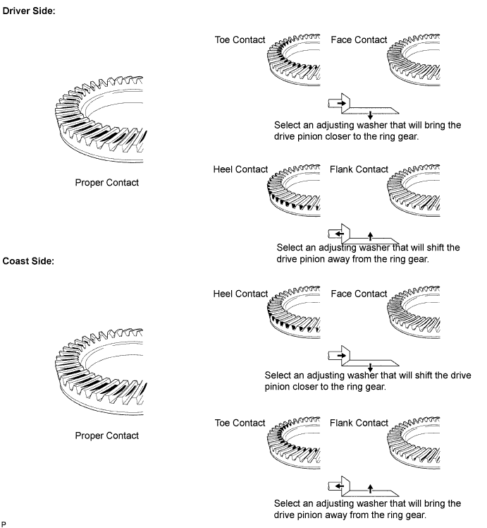
| Thickness mm (in.) | Thickness mm (in.) |
| 1.70 (0.0669) | 2.03 (0.0799) |
| 1.73 (0.0681) | 2.06 (0.0811) |
| 1.76 (0.0693) | 2.09 (0.0823) |
| 1.79 (0.0705) | 2.12 (0.0835) |
| 1.82 (0.0717) | 2.15 (0.0847) |
| 1.85 (0.0728) | 2.18 (0.0853) |
| 1.88 (0.0740) | 2.21 (0.0870) |
| 1.91 (0.0752) | 2.24 (0.0882) |
| 1.94 (0.0764) | 2.27 (0.0894) |
| 1.97 (0.0776) | 2.30 (0.0906) |
| 2.00 (0.0787) | 2.33 (0.0917) |
| 15. REMOVE REAR DRIVE PINION NUT |
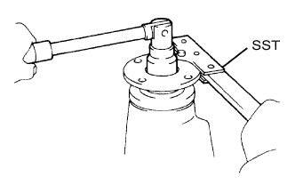 |
Using SST to hold the drive pinion companion flange, remove the nut.
| 16. REMOVE REAR DRIVE PINION COMPANION FLANGE SUB-ASSEMBLY REAR |
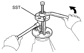 |
Using SST, remove the drive pinion companion flange.
| 17. REMOVE REAR DRIVE PINION FRONT TAPERED ROLLER BEARING |
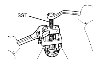 |
Using SST, remove the drive pinion tapered roller bearing from the drive pinion.
| 18. INSTALL REAR DIFFERENTIAL DRIVE PINION BEARING SPACER |
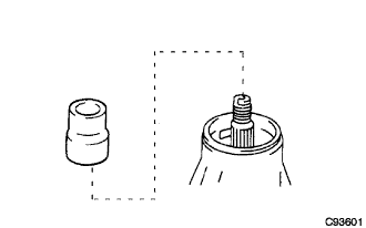 |
Install a new bearing spacer onto the drive pinion.
| 19. INSTALL REAR DRIVE PINION FRONT TAPERED ROLLER BEARING |
|
Install the drive pinion, rear drive pinion taper roller bearing and rear differential drive oil slinger.
| 20. INSTALL REAR DIFFERENTIAL CARRIER OIL SEAL |
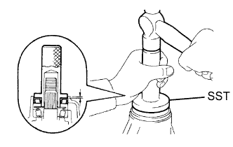 |
Apply MP grease to the oil seal lip.
Using SST and a hammer, install a new carrier oil seal.
| 21. INSTALL REAR DRIVE PINION COMPANION FLANGE SUB-ASSEMBLY REAR |
|
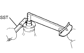
Using SST, install the drive pinion companion flange onto the drive pinion.
 |
Coat the threads of a new nut with hypoid gear oil LSD.
Using SST to hold the flange, tighten the nut.
| 22. INSPECT DRIVE PINION PRELOAD |
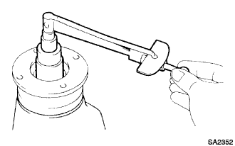 |
Using a torque wrench, measure the preload of the backlash between the drive pinion and ring gear.
| Bearing | Standard |
| New | 1.05 to 1.64 N*m (10.7 to 16.7 kgf*cm, 9.3 to 14.5 in.*lbf) |
| Reused | 0.56 to 0.85 N*m (5.7 to 8.7 kgf*cm, 4.9 to 7.5 in.*lbf) |
| 23. INSPECT TOTAL PRELOAD |
|
Using a torque wrench, measure the preload.
| 24. INSPECT DIFFERENTIAL RING GEAR BACKLASH |
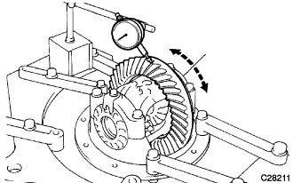 |
Using a dial indicator, check the backlash of the ring gear.
| 25. INSPECT RUNOUT OF REAR DRIVE PINION COMPANION FLANGE SUB-ASSEMBLY REAR |
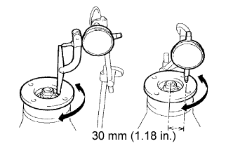 |
Using a dial indicator, measure the runout of the drive pinion companion flange vertically and horizontally.
| 26. INSTALL REAR DRIVE PINION NUT |
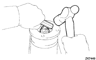 |
Using a chisel and hammer, stake the drive pinion nut.
| 27. INSTALL REAR DIFFERENTIAL BEARING ADJUSTING NUT LOCK |
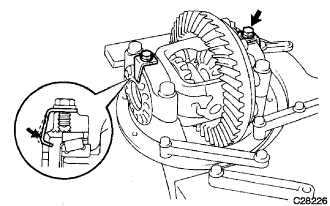 |
Install 2 new adjust locks onto the bearing caps.
After tightening the bolts, bend the nut locks.
| 28. INSTALL REAR DIFFERENTIAL LOCK SHIFT FORK |
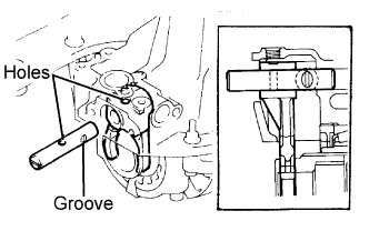 |
Apply MP grease onto the outer circuit of the shaft.
Install the fork shaft to align the hole of the shift fork with that of the shift fork shaft.
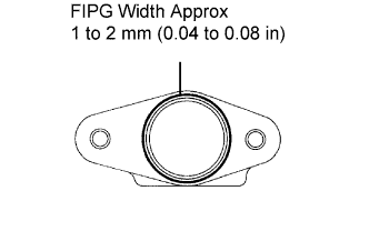 |
Remove any FIPG material and be careful not to drop the oil shaft retainer.
Apply FIPG to the carrier, as shown in the illustration.
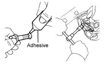 |
Clean the threads of the bolts and retainer bolts holes with toluene or trichorethyene.
Apply adhesive to 2 or 3 threads of each mount bolt end.
Tighten the shaft retainer with the 2 bolts.
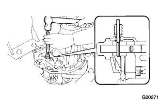 |
Using a 5 mm pin punch and hammer, install the slotted spring pin onto the shift fork.
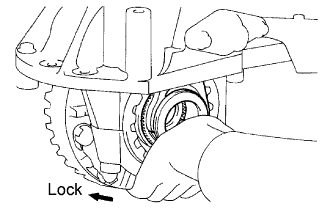 |
Push the differential lock sleeve in deeply and hold it in position.
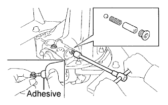 |
Install the ball, spring and spring seat.
Clean the threads of 2 plugs and plug holes with toluene or trichlorethylene.
Using a 6 mm hexagon wrench, install and tighten the screw plugs.
| 29. INSTALL NO.1 TRANSFER INDICATOR SWITCH |
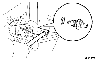 |
Install the indicator switch with a new gasket.
| 30. INSPECT REAR DIFFERENTIAL LOCK SLEEVE |
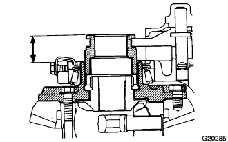 |
Measure the distance between the sleeve and tip of the differential case when the differential is FREE and LOCKED respectively.
| 31. INSTALL DIFFERENTIAL LOCK SHIFT ACTUATOR |
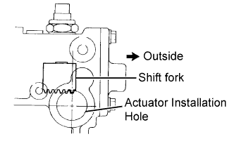 |
Check that the outermost rack tooth of the shift fork is virtually above the center line of the actuator installation hole.
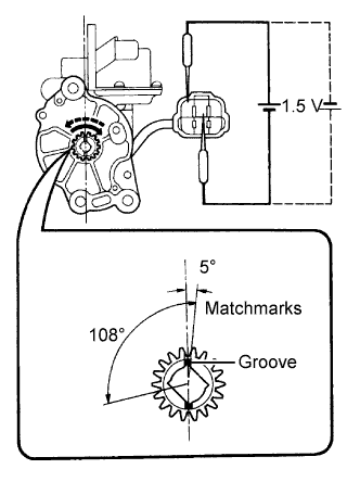 |
Ensure that the matchmarks on the pinion of the actuator are in the range between 0 and 5 degrees clockwise above the center line of the actuator.
Install a new O-ring onto the actuator.
Apply a light coat of gear oil to the O-ring.
Apply MP grease to the gear part.
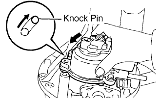 |
Ensure that the outermost rack tooth of the shift fork fits the matchmarks on the pinion of the actuator.
Install the actuator so that the long hole on the actuator side fits into the knock pin on the carrier side.
Align the actuator with the long hole and rotate the actuator counterclockwise when the knock pin is set to the right-hand side.
Install and tighten the bolts.