TOUCH SELECT 2-4 AND HIGH-LOW SYSTEM > INSPECTION |
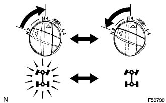
| 1. INSPECT H2 (2WD) - H4 (4WD) SHIFT |
|
Start the engine.
Turn the 4 wheel drive control switch from the H2 to the H4 position.
Check that the 4WD indicator light blinks and then stays on.
Turn the 4 wheel drive control switch from the H4 to the H2 position
Check that the 4WD indicator light blinks and then goes off.
| 2. INSPECT H4 (4WD) - L4 (4WD) SHIFT |
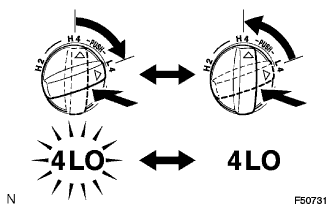 |
Start the engine.
Turn the 4 wheel drive control switch from the H4 to the L4 position while pressing it.
Check that the 4LO indicator light blinks and then stays on.
Turn the 4 wheel drive control switch from the L4 to the H4 position while pressing it.
Check that the 4LO indicator light blinks and then goes off.
| 3. INSPECT H2 (2WD) - L4 (4WD) SHIFT |
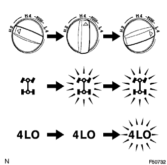 |
Start the engine.
Turn the 4 wheel drive control switch from the H2 to the H4 position.
Check that the 4WD indicator light blinks and then stays on.
Turn the 4 wheel drive control switch from the H4 to the L4 position while pressing it.
Check that the 4LO indicator light blinks and then stays on.
| 4. INSPECT L4 (4WD) - H2 (2WD) SHIFT |
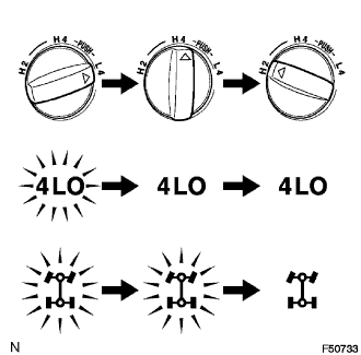 |
Start the engine.
Turn the 4 wheel drive control switch from the L4 to the H4 position while pressing it.
Check that the 4LO indicator light blinks and then goes off.
Turn the 4 wheel drive control switch from the H4 to the H2 position.
Check that the 4WD indicator light blinks and then goes off.
| 5. INSPECT 4 WHEEL DRIVE CONTROL SWITCH |
Remove the center instrument cluster finish panel sub-assembly.
Remove the 4 wheel drive control switch from the center instrument cluster finish panel sub-assembly.
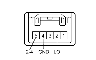 |
Using an ohmmeter, measure the resistance between the terminals.
| Switch position | Tester connection | Specified condition |
| H2 | 5 (2-4) - 4 (GND) | Below 1Ω |
| H4 | 5 (2-4) → 4 (GND) | Below 1Ω |
| 5 (2-4) ← 4 (GND) | 100 kΩ or higher | |
| 2 (LO) → 4 (GND) | Below 1Ω | |
| 2 (LO) ← 4 (GND) | 100 kΩ or higher | |
| L4 | 2 (LO) - 4 (GND) | Below 1Ω |
| 6. INSPECT ACTUATOR RESISTANCE |
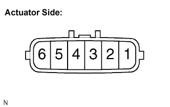 |
Using an ohmmeter, measure the resistance between terminals 1 and 2.
Using an ohmmeter, measure the resistance between terminals 1 or 2 and the body ground.
| 7. INSPECT ACTUATOR OPERATION |
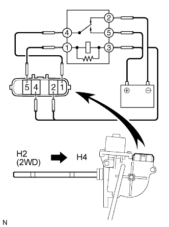 |
H2 (2WD) → H4 shift:
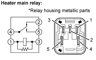
Connect the lines via the relay as shown in the illustration, then check that the actuator fork shaft moves from the H2 (2WD) to the H4 positions.
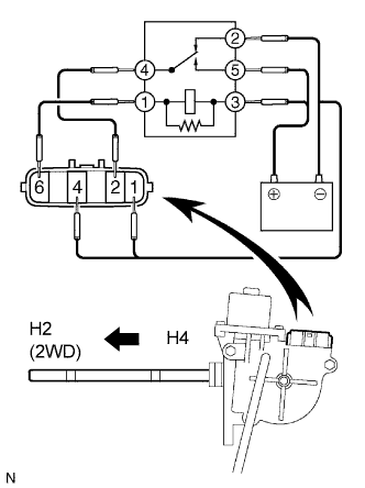 |
H4 → H2 (2WD) shift:
Connect the lines via the relay as shown in the illustration, then check that the actuator fork shaft moves from the H4 to the H2 (2WD) positions.
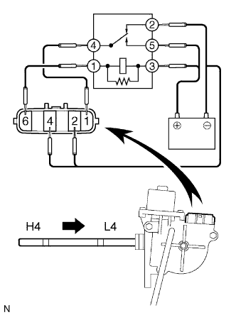 |
H4 → L4 shift:
Connect the lines via the relay as shown in the illustration, then check that the actuator fork shaft moves from the H4 to the L4 positions.
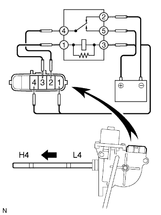  |
L4 →H4 shift:
Connect the lines via the relay as shown in the illustration, then check that the actuator fork shaft moves from the L4 to the H4 positions.
| 8. INSPECT LIMIT SWITCH CONTINUITY |
|
Start the engine and lift the vehicle up.
With the actuator connector connected, after checking the operating sound, disconnect the connector and inspect the continuity between the terminals using an ohmmeter.
| Shift position | Tester connection | Specified condition |
| H2 | 3 - 4 3 - 5 3 - 6 4 - 5 4 - 6 5 - 6 | 100 kΩ or higher 100 kΩ or higher 100 kΩ or higher Below 1Ω 100 kΩ or higher 100 kΩ or higher |
| H4 | 3 - 4 3 - 5 3 - 6 4 - 5 4 - 6 5 - 6 | 100 kΩ or higher 100 kΩ or higher 100 kΩ or higher 100 kΩ or higher Below 1Ω 100 kΩ or higher |
| L4 | 3 - 4 3 - 5 3 - 6 4 - 5 4 - 6 5 - 6 | Below 1Ω 100 kΩ or higher 100 kΩ or higher 100 kΩ or higher 100 kΩ or higher 100 kΩ or higher |
| 9. INSPECT 4 WHEEL DRIVE CONTROL ECU |
Connect the wire harness side connector to the 4 wheel drive control ECU and inspect the wire harness side connector from the back side, as shown.
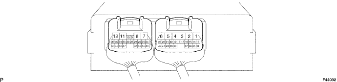
| Terminals (Symbols) | Condition | STD Voltage (V) |
| 2 (TM1) - 1 (TM2) |
| 10 to 14 or 0 to 14 pulse generation then less than 0.5 |
| 1 (TM2) - 2 (TM1) |
| 10 to 14 or 0 to 14 pulse generation then less than 0.5 |
| 3 (DM1) - 4 (DM2) |
| 10 to 14 or 0 to 14 pulse generation then less than 0.5 |
| 4 (DM2) - 3 (DM1) |
| 10 to 14 or 0 to 14 pulse generation then less than 0.5 |
| 12 (GND) - Body ground | Ignition switch OFF | Below 1Ω |
| 11 (IG) - 12 (GND) | Ignition switch ON | 10 to 14 |
| 18 (DL2) - 12 (GND) |
| 1.5 or less → 10 to 14 |
| 19 (DL1) - 12 (GND) |
| 1.5 or less → 10 to 14 |
| 25 (2-4) - 12 (GND) |
| 10 to 14 → 2 or less |
| 26 (SPD) - 12 (GND) | During driving | Pulse generation |
| 28 (IND3) - 12 (GND) |
| 10 to 14 → 1.5 to 3.5 |
| 32 (LO) - 12 (GND) |
| 10 to 14 →1.5 or less |
| 42 (ADD) - 12 (GND) |
| 10 to 14 →1.5 or less |
| 23 (L4) - 12 (GND) |
| 10 to 14 →1.5 or less |
| 38 (4WD) - 12 (GND) |
| 10 to 14 →1.5 or less |
| 39 (TL3) - 12 (GND) |
| 10 to 14 → 0.88 or less |
| 40 (TL2) - 12 (GND) |
| 10 to 14 → 0.88 or less |
| 41 (TL1) - 12 (GND) |
| 0.88 or less → 10 to 14 |
| 45 (IND1) - 12 (GND) |
| 10 to 14 → 0 to 3.5 |
| 48 (N) - 12 (GND) |
| 1.5 or less → 10 to 14 |