TRANSFER ASSEMBLY > DISASSEMBLY |
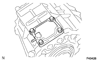
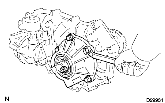
| 1. REMOVE TRANSFER CASE COVER SUB-ASSEMBLY |
|
Remove the 4 bolts and the case cover sub-assembly.
| 2. REMOVE BREATHER OIL DEFLECTOR SUB-ASSEMBLY |
| 3. REMOVE TRANSFER RH BEARING RETAINER SUB-ASSEMBLY |
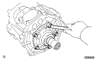 |
Remove the 5 bolts and the front bearing retainer sub-assembly.
| 4. REMOVE TRANSFER RH BEARING RETAINER OIL SEAL (for R155F/A750F) |
Using a screwdriver and hammer, remove the transfer RH bearing retainer oil seal.
| 5. REMOVE TRANSFER RH BEARING RETAINER OIL SEAL (for RA60F) |
Using a screwdriver and hammer, remove the 2 transfer RH bearing retainer oil seals.
| 6. REMOVE OUTPUT SHAFT COMPANION FLANGE SUB-ASSEMBLY |
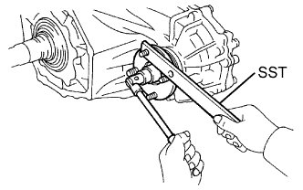 |
Using a chisel and hammer, loosen the staked part of the output shaft companion flange lock nut.
Using SST to hold the output shaft companion flange, remove the output shaft companion flange lock nut.
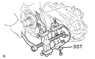 |
Using SST, remove the output shaft companion flange sub-assembly (front side).
| 7. REMOVE TRANSFER OUTPUT SHAFT COMPANION FLANGE OIL SEAL |
Using a screwdriver and hammer, remove the companion flange oil seal.
| 8. REMOVE OUTPUT SHAFT COMPANION FLANGE SUB-ASSEMBLY |
Remove the rear output shaft companion flange sub-assembly using the same procedure as for the front output shaft companion flange sub-assembly (rear side).
| 9. REMOVE TRANSFER OUTPUT SHAFT COMPANION FLANGE OIL SEAL |
Using a screwdriver and hammer, remove the companion flange oil seal.
| 10. REMOVE SPEEDOMETER DRIVEN GEAR SUB-ASSEMBLY (for R155F/RA60F) |
Remove the bolt and speedometer driven gear w/ sensor.
| 11. REMOVE SPEEDOMETER DRIVEN HOLE COVER SUB-ASSEMBLY (for A750F) |
Remove the bolt and speedometer hole cover sub-assembly.
| 12. REMOVE TRANSFER EXTENSION HOUSING SUB-ASSEMBLY FRONT |
 |
Remove the 5 bolts and extension housing sub-assembly.
| 13. REMOVE TRANSFER EXTENSION HOUSING TYPE T OIL SEAL |
Using a screwdriver and hammer, remove the type T oil seal.
| 14. REMOVE TRANSFER OUTPUT WASHER |
| 15. REMOVE TRANSFER SPEEDOMETER DRIVE GEAR |
Remove the speedometer drive gear.
Using a magnetic finger, remove the speedometer drive gear ball.
| 16. REMOVE TRANSFER REAR CASE |
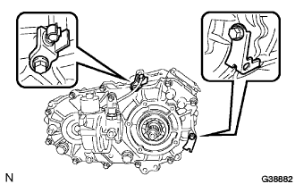 |
Remove the 12 bolts and 2 brackets.
Remove the transfer case rear.
| 17. REMOVE TRANSFER FRONT DRIVE SHIFT FORK SHAFT |
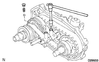 |
Using a hexagon wrench (6 mm), remove the 2 shift detent ball spring plugs, 2 shift fork compression springs and 2 shift detent balls.
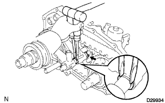 |
Using 2 screwdrivers and a hammer, tap out the 2 shift fork shaft snap rings.
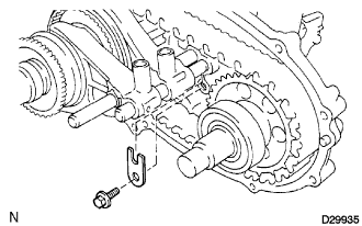 |
Remove the bolt and shift shaft stopper.
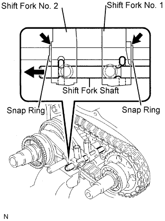 |
To pull out the shift fork shaft, shift the shift fork No. 1 and No. 2 to the positions shown in the illustration.
Pull out the shift fork shaft.
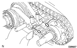 |
Using a magnetic finger, remove the 2 shift inter lock pins.
| 18. REMOVE REAR OUTPUT SHAFT ASSEMBLY, FRONT DRIVE CHAIN, DRIVEN SPROCKET ASSEMBLY, SHIFT FORK NO. 1 AND NO. 2 |
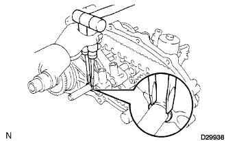 |
Using 2 screwdrivers and a hammer, tap out the shift fork shaft snap ring.
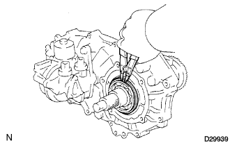 |
Using a snap ring expander, remove the output shaft snap ring.
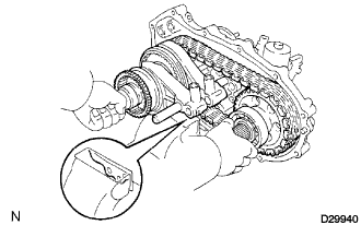 |
Mount the transfer case rear in a vise.
Using a plastic hammer, carefully tap the transfer case rear and remove the rear output shaft assembly, driven sprocket assembly, front drive chain, shift fork No. 1 and No. 2.
Remove the driven sprocket assembly, front drive chain, shift fork No. 1 and No. 2 from the rear output shaft assembly.
| 19. REMOVE TRANSFER SHIFT ACTUATOR ASSEMBLY |
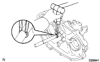 |
Using 2 screwdrivers and a hammer, remove the shift fork shaft snap ring.
Remove the 3 bolts and shift actuator assembly.
| 20. REMOVE TRANSFER INDICATOR SWITCH NO.1 |
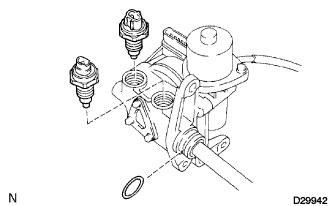 |
Remove the O-ring, the 2 indicator switches No. 1 and 2 gaskets.
| 21. REMOVE TRANSFER DRIVEN SPROCKET BEARING |
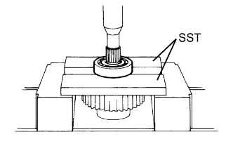 |
Using SST and a press, remove the driven sprocket bearing.
| 22. REMOVE TRANSFER INPUT GEAR RADIAL BALL BEARING |
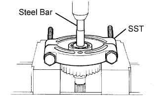 |
Using SST, a press and steel bar, remove the input gear radial ball bearing.
| 23. REMOVE TRANSFER CASE PLUG |
Remove the transfer case plug No. 1 (filler plug) and gasket.
| 24. REMOVE TRANSFER CASE PLUG |
Remove the transfer case plug (drain plug) and gasket.
| 25. REMOVE TRANSFER OIL SEPARATOR SUB-ASSEMBLY |
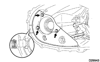 |
Remove the 3 bolts and oil separator sub-assembly.
| 26. REMOVE TRANSFER CASE MAGNET |
| 27. REMOVE TRANSFER OIL PUMP BODY SUB-ASSEMBLY |
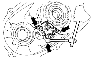 |
Remove the 3 bolts and oil pump body sub-assembly.
| 28. REMOVE TRANSFER OIL PUMP GEAR |
| 29. REMOVE TRANSFER OIL PUMP BODY O-RING |
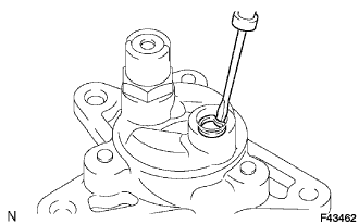 |
Using a screwdriver, remove the oil pump body O-ring.
| 30. REMOVE LOW PLANETARY GEAR ASSEMBLY WITH INPUT SHAFT SUB-ASSEMBLY |
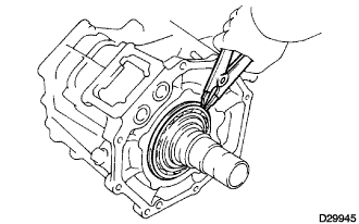 |
Using a snap ring expander, remove the low planetary gear bearing shaft snap ring.
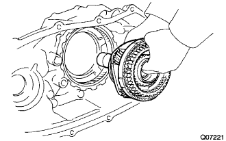 |
Remove the low planetary gear assembly w/ input shaft assembly.
| 31. REMOVE TRANSFER CASE PLUG |
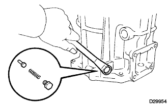 |
Remove the case plug.
Using a magnetic finger, remove the spring and pin.
| 32. REMOVE TRANSFER LOW PLANETARY RING GEAR |
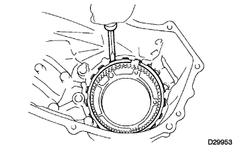 |
Using a screwdriver, remove the hole snap ring.
Remove the low planetary ring gear from the front case.
| 33. REMOVE TRANSFER CASE OIL SEAL |
Using a screwdriver and hammer, remove the transfer case oil seal.
| 34. REMOVE TRANSFER LOW PLANETARY GEAR SPLINE PIECE |
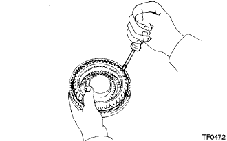 |
Using a screwdriver, remove the low planetary gear shaft snap ring.
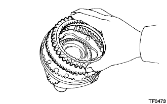 |
Remove the low planetary gear spline piece.
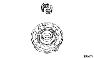
| 35. REMOVE TRANSFER OUTPUT SHAFT FRONT NEEDLE ROLLER BEARING |
 |
| 36. REMOVE TRANSFER INPUT GEAR STOPPER SHAFT SNAP RING |
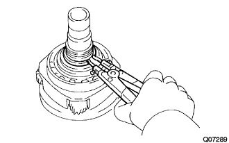 |
Using a snap ring expander, remove the input gear stopper shaft snap ring.
| 37. REMOVE TRANSFER INPUT GEAR STOPPER |
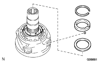 |
| 38. REMOVE TRANSFER INPUT GEAR STOPPER BALL |
| 39. REMOVE MANUAL TRANSFER PLANETARY CARRIER WASHER |
| 40. REMOVE TRANSFER INPUT SHAFT |
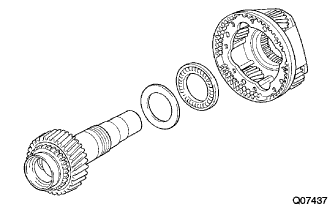 |
| 41. REMOVE TRANSFER NO. 1 THRUST BEARING RACE |
| 42. REMOVE TRANSFER LOW PLANETARY GEAR BEARING |
| 43. REMOVE TRANSFER NO. 1 INPUT SHAFT SEAL RING |
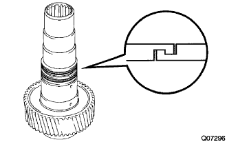 |
Remove the 2 seal rings No. 1.
| 44. REMOVE TRANSFER INPUT SHAFT BEARING |
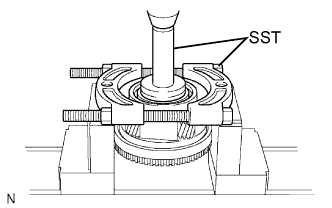 |
Using a snap ring expander, remove the input bearing shaft snap ring.
Using SST and a press, remove the input shaft bearing.
| 45. REMOVE TRANSFER LOW PLANETARY GEAR BEARING |
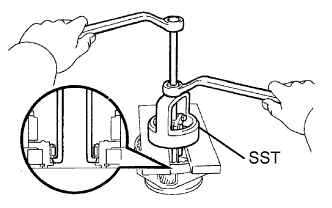 |
Using SST, remove the low planetary gear bearing.
| 46. INSPECT DRIVE SPROCKET THRUST CLEARANCE |
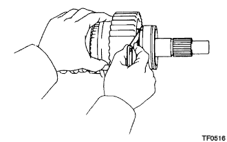 |
Using a feeler gauge, measure the drive sprocket thrust clearance.
| 47. REMOVE TRANSFER CLUTCH HUB |
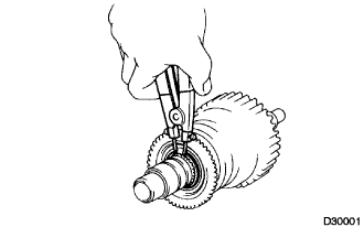 |
Using a snap ring expander, remove the clutch hub shaft snap ring.
Remove the high and low clutch sleeve.
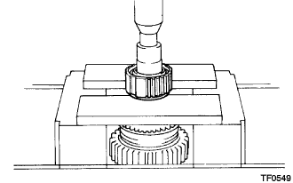 |
Using a press, remove the clutch hub.
| 48. REMOVE TRANSFER OUTPUT SHAFT REAR RADIAL BALL BEARING |
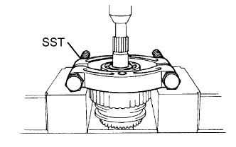 |
Using SST and a press, remove the bearing.
| 49. REMOVE TRANSFER DRIVE SPROCKET SUB-ASSEMBLY |
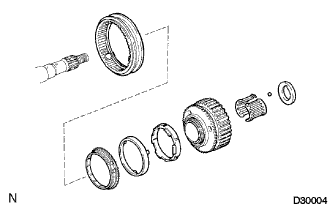 |
Remove the output shaft spacer and output shaft spacer ball.
Remove the drive sprocket sub-assembly, synchronizer inner ring, center ring, outer ring and drive clutch sleeve together.
Remove the drive sprocket bearing.
Remove the synchronizer inner ring, center ring, outer ring and drive clutch sleeve.
Remove the 3 synchromesh shifting keys No. 1 and the 2 synchromesh shifting key springs No. 1.