AUTOMATIC TRANSMISSION ASSEMBLY > INSTALLATION |
| 1. INSPECT TORQUE CONVERTER CLUTCH ASSEMBLY |
|
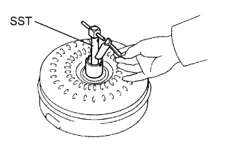
Inspect the one-way clutch.
Install SST into the inner race of the one-way clutch.
Set SST so that it fits in the notch of the converter hub and outer race of the one-way clutch.
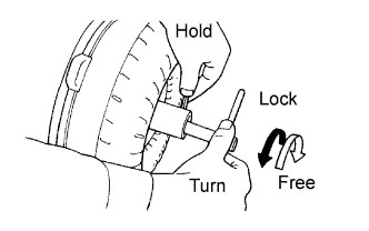 |
With the torque converter standing on its side, check that the clutch locks when turned counterclockwise and rotates freely and smoothly clockwise.
If necessary, clean the converter and check the one-way clutch again.
Replace the converter if the one-way clutch still doesn't operate as specified.
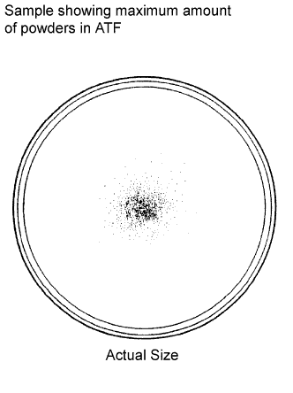 |
Check the condition of the torque converter clutch assembly.
If the inspection result of the torque converter clutch assembly matches any of the cases mentioned below, replace the torque converter clutch.
Replace the ATF in the torque converter clutch.
If the ATF is discolored and/or has a foul odor, completely stir the ATF in the torque converter clutch and drain it with the installation surface facing up.
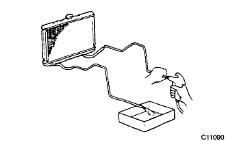 |
Clean and then check the oil cooler and oil pipe line.
If inspecting the torque converter clutch or exchanging the ATF, clean the oil cooler and oil pipe line.
If the ATF is cloudy, inspect the oil cooler (radiator).
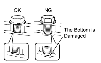 |
Be careful not to deform the torque converter clutch or damage the oil pump gear.
When any marks due to interference are found on the end of the bolt on the torque converter clutch and on the bottom of the bolt hole, replace the bolt and the torque the converter clutch.
All the bolts should be the same length.
Do not lose any spring washers.
| 2. INSTALL TORQUE CONVERTER CLUTCH ASSEMBLY |
Install the torque converter clutch onto the automatic transmission.
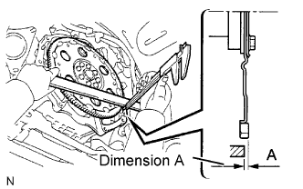 |
Using calipers and a straight edge, measure dimension A, between the transmission and the end surface of the drive plate, as shown in the illustration.
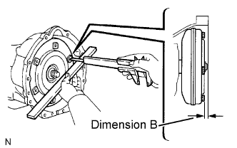 |
Using calipers and a straight edge, measure the dimension B shown in the illustration and check that B is greater than A measured in (b).
| 3. INSTALL REAR NO.1 ENGINE MOUNTING INSULATOR |
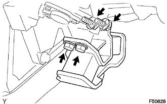 |
Install the engine mounting insulator with the 4 bolts.
| 4. INSTALL NO.1 TRANSMISSION CONTROL CABLE BRACKET |
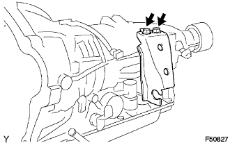 |
Install the transmission control cable bracket No. 1 with the 2 bolts.
| 5. INSTALL AUTOMATIC TRANSMISSION ASSEMBLY |
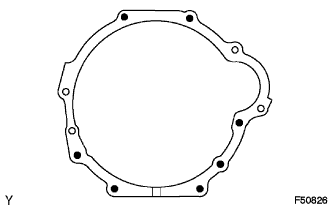 |
Install the automatic transmission with the 7 bolts.
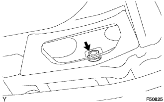 |
Install the 6 torque converter clutch mounting bolts.
Install the flywheel housing under cover.
| 6. INSTALL WIRE HARNESS |
| 7. INSTALL STARTER ASSEMBLY |
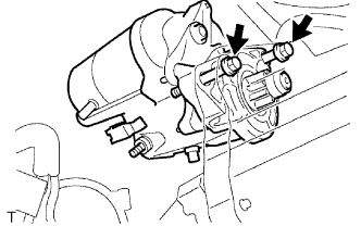 |
Install the starter with the 2 bolts.
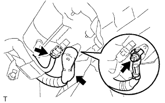 |
Connect the starter connector.
Install the starter wire harness with the nut.
Install the terminal cap.
| 8. INSTALL NO.3 FRAME CROSSMEMBER SUB-ASSEMBLY |
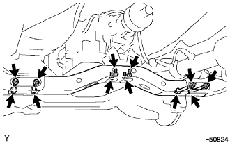 |
Install the frame crossmember sub-assembly No. 3 with the 4 bolts and 4 nuts.
Install the frame crossmember sub-assembly No. 3 with the 4 bolts.
Connect the heated oxygen sensor connector.
| 9. INSTALL FRONT SUSPENSION MEMBER BRACKET |
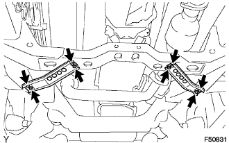 |
Install the 2 front suspension member brackets with the 8 bolts.
| 10. INSTALL FLOOR SHIFT GEAR SHIFTING ROD SUB-ASSEMBLY |
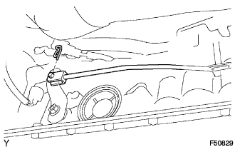 |
ROD TYPE:
Install the floor shift gear shifting rod, then install the clip.
| 11. CONNECT TRANSMISSION CONTROL CABLE ASSEMBLY |
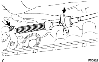 |
CABLE TYPE:
Connect the transmission control cable with the clip.
Connect the transmission control cable with the nut.
| 12. INSTALL MANIFOLD STAY |
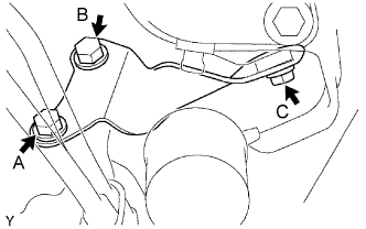 |
Install the manifold stay with the 3 bolts.
| 13. INSTALL NO.1 OIL COOLER INLET TUBE |
Provisionally install the oil cooler inlet tube No. 1.
Provisionally install the oil cooler outlet tube No. 1.
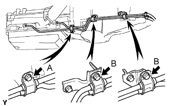 |
Install the 3 clamps and 3 bolts.
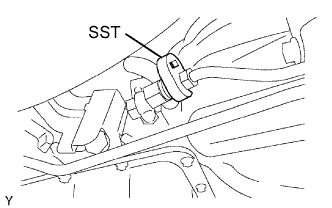 |
Using SST, tighten the oil cooler inlet tube No. 1.
| 14. INSTALL NO.1 OIL COOLER OUTLET TUBE |
Using SST, tighten the oil cooler outlet tube No. 1.
| 15. INSTALL TRANSMISSION OIL FILLER TUBE SUB-ASSEMBLY |
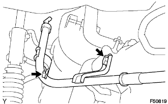 |
Coat new O-ring with ATF and install it onto the oil filler tube.
Install the oil filler tube with the 2 bolts.
| 16. INSTALL TRANSMISSION OIL LEVEL GAGE SUB-ASSEMBLY |
| 17. INSTALL PROPELLER WITH CENTER BEARING SHAFT ASSEMBLY (for Except Regular Cab) |
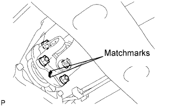 |
Align the matchmarks on the yoke and transfer flange.
Install the propeller shaft with the 4 nuts and 4 washers.
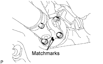 |
Align the matchmarks on the yoke and differential flange.
Install the propeller shaft with the 4 bolts, 4 nuts and 4 washers.
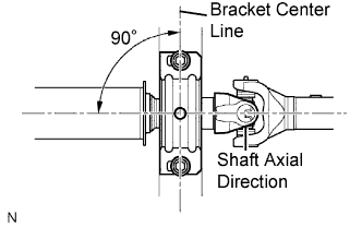 |
Provisionally install the center support bearing with 2 mounting bolts.
Torque the 2 bolts.
| 18. INSTALL PROPELLER SHAFT ASSEMBLY (for Regular Cab) |
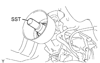 |
Remove SST from the extension housing.
Install the propeller shaft assembly into the extension housing.
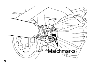 |
Align the matchmarks on the propeller shaft flange and differential flange.
Install the propeller shaft assembly with the 4 bolts, 4 nuts and 4 washers.
| 19. ADJUST SHIFT LEVER POSITION |
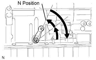 |
Push the control shaft fully rearward.
Turn the control shaft lever 2 notches counterclockwise to the N position.
Set the shift lever to the N position.
| 20. CONNECT CABLE TO NEGATIVE BATTERY TERMINAL |
| 21. ADD AUTOMATIC TRANSMISSION FLUID |
| 22. INSPECT AUTOMATIC TRANSMISSION FLUID |
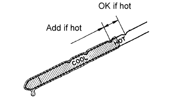 |
Park the vehicle on a level surface and engage the parking brake.
With the engine idling and the brake pedal depressed, shift the shift lever into all positions from P to L, and then return it to the P position.
Pull out the oil level gage and wipe it clean.
Push it back fully into the pipe.
Pull it out and check that the fluid level is within the HOT range.
If there is any leakage, repair or replace O-rings, FIPGs, oil seals, plugs or other parts.
| 23. INSPECT SHIFT LEVER POSITION |
Check that the shift lever moves smoothly and appropriately from the P to R position, only when the ignition switch is turned to ON and the brake pedal is depressed.
When starting the engine, make sure that the vehicle moves forward when shifting the lever from the N to D position and moves rearward when shifting the lever to the R position.