FRONT PROPELLER SHAFT ASSEMBLY (for 4WD) > INSTALLATION |
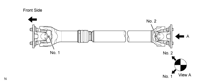
| 1. INSPECT FRONT PROPELLER SHAFT ASSEMBLY |
| 2. INSTALL FRONT PROPELLER SHAFT ASSEMBLY |
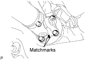 |
Align the matchmarks on the yoke and differential flange.
Install the propeller shaft with the 4 bolts, 4 nuts and 4 washers.
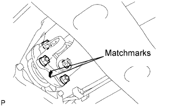 |
Align the matchmarks on the yoke and transfer flange.
Install the propeller shaft with the 4 nuts and 4 washers.
| 3. REMOVE PROPELLER SHAFT HEAT INSULATOR BRACKET SUB-ASSEMBLY |
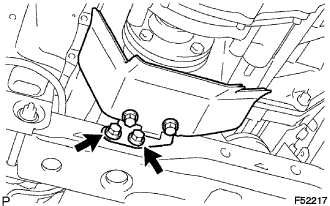 |
Install the propeller shaft heat insulator bracket with the 2 bolts.
| 4. REMOVE EXHAUST FRONT PIPE ASSEMBLY NO. 2 (for 1GR-FE) |
Install a new gasket onto the exhaust manifold LH.
Install a new gasket onto the exhaust front pipe.
Install the exhaust front pipe No. 2 onto the insulator.
Install the exhaust front pipe No. 2 onto the exhaust manifold LH with the new 2 nuts.
Install the exhaust front pipe No. 2 onto the exhaust front pipe with the 2 bolts and 2 nuts.
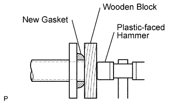 |
Install a new gasket onto the exhaust front pipe No. 2.
Using a wooden block and plastic- faced hammer, tap in a new gasket until it is flush with the exhaust front pipe No. 2.