REAR PROPELLER SHAFT ASSEMBLY (for Access Cab 4WD and Double Cab 4WD) > DISASSEMBLY |
| 1. INSPECT PROPELLER SHAFT UNIVERSAL JOINT SPIDER BEARING |
Check the spider bearings for wear and damage.
Check each spider bearing's axial play by turning the yoke while holding the shaft tightly.
| 2. REMOVE PROPELLER SHAFT UNIVERSAL JOINT SPIDER BEARING |
|
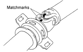
Place matchmarks on the propeller shaft and universal joint yoke.
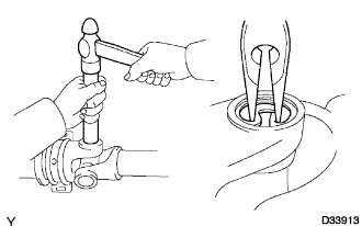 |
Using a brass bar and hammer, slightly tap in the spider bearing.
Using needle-nose pliers, remove the 4 snap rings from the grooves.
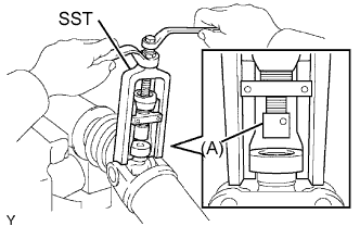 |
Clamp the propeller shaft in a vise between aluminum plates.
Using SST, push the spider bearing out of the propeller shaft.
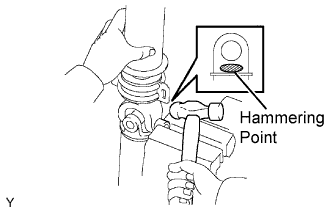 |
Clamp the removed spider bearing outer race in a vise and tap the propeller shaft to remove the spider bearing.
Separate the propeller with center bearing shaft.
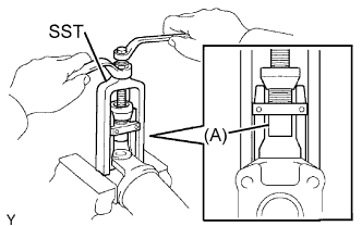 |
Reinstall the 2 removed spider bearings onto the spider and clamp the spider bearings in a vise.
Using SST, push the bearing out of the yoke.
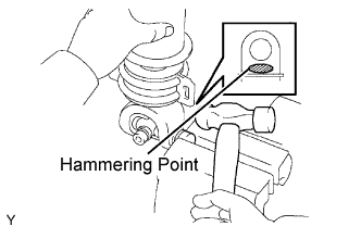 |
Clamp the outer bearing race in a vise and tap off the yoke with a hammer.
Remove the spider.
| 3. REMOVE CENTER SUPPORT BEARING ASSEMBLY NO. 2 |
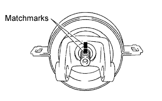 |
Fix the yoke at the center bearing section in a vice.
Using a chisel and a hammer, loosen the staked part of the lock nut.
Place matchmarks on the yoke and shaft.
Using a brass bar and hammer, remove the center yoke, spacer and center support bearing from the intermediate shaft.