 |
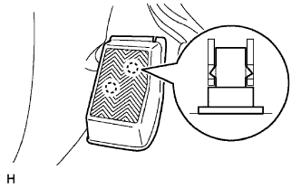
Disengage the 2 clips and remove the front floor footrest.
HYDRAULIC BRAKE BOOSTER (w/ VSC) > REMOVAL |
| 1. DISCONNECT CABLE FROM NEGATIVE BATTERY TERMINAL |
| 2. DRAIN BRAKE FLUID |
| 3. REMOVE FRONT FLOOR FOOTREST |
|
Disengage the 2 clips and remove the front floor footrest.
| 4. REMOVE FRONT DOOR SCUFF PLATE (for Regular Cab) |
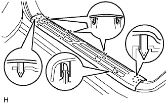 |
Disengage the 8 claws and clip, and remove the front door scuff plate.
| 5. REMOVE FRONT DOOR SCUFF PLATE (for Access Cab) |
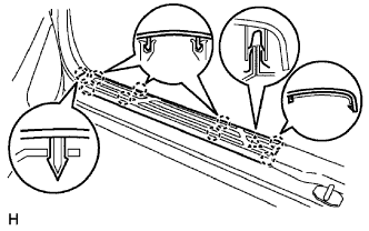 |
Disengage the 9 claws and clip, and remove the front door scuff plate.
| 6. REMOVE FRONT DOOR SCUFF PLATE (for Double Cab) |
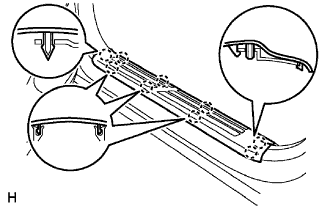 |
Disengage the 9 claws and remove the front door scuff plate.
| 7. REMOVE COWL SIDE TRIM BOARD (for Regular Cab) |
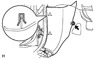 |
Remove the clip.
Disengage the 2 clips and remove the cowl side trim board.
| 8. REMOVE COWL SIDE TRIM BOARD (for Access Cab) |
|
Remove the clip.
Disengage the 2 clips and remove the cowl side trim board.
| 9. REMOVE COWL SIDE TRIM BOARD (for Double Cab) |
|
Remove the clip.
Disengage the 2 clips and remove the cowl side trim board.
| 10. REMOVE INSTRUMENT PANEL UNDER TRAY (for Automatic Transmission) |
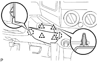 |
Disengage the 4 clips and 2 claws, and remove the instrument panel under tray.
| 11. REMOVE INSTRUMENT PANEL HOLE COVER (for Manual Transmission) |
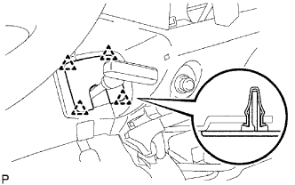 |
Disengage the 4 clips and remove the instrument panel hole cover.
| 12. REMOVE INSTRUMENT PANEL FINISH PANEL LOWER NO. 1 |
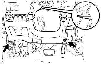 |
Remove the 2 bolts <B>.
Disengage the 3 clips and remove the lower No. 1 instrument panel finish panel.
Disconnect the connectors.
| 13. SEPARATE DRIVER SIDE JUNCTION BLOCK |
| 14. SEPARATE MASTER CYLINDER PUSH ROD CLEVIS |
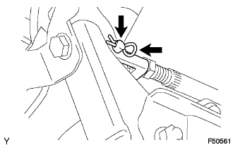 |
Remove the clip and push rod pin, then separate the push rod clevis.
| 15. REMOVE HYDRAULIC BRAKE BOOSTER |
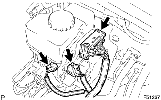 |
Disconnect the 3 connectors from the hydraulic brake booster.
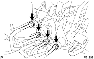 |
Using SST, disconnect the 4 brake lines from the hydraulic brake booster.
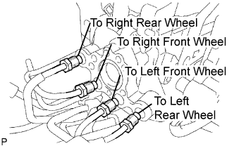 |
Use tags or labels to identify the place to reconnect each line.
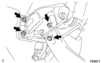 |
Remove the 4 nuts and pull out the hydraulic brake booster.
Remove the brake booster gasket.