Home › BRAKE › BRAKE › BRAKE MASTER CYLINDER (w/o VSC)

BRAKE MASTER CYLINDER (w/o VSC) > INSTALLATION

for Preparation Click here


1. INSPECT AND ADJUST BRAKE BOOSTER PUSH ROD

NOTICE:
Make adjustments while the brake booster has no vacuum in it. (Depress the brake pedal several times with the engine stopped.)

HINT:
The brake booster push rod should be adjusted when the brake master cylinder is replaced with a new one. The adjustment is not necessary when the brake master cylinder is reinstalled and the brake booster is replaced with a new one.

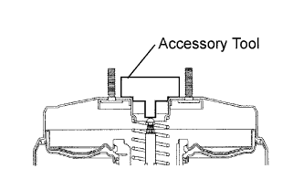
  1. Apply chalk to the tip of an accessory tool.

    HINT:
    An accessory tool is enclosed with a new brake master cylinder sub-assembly.


    F044323E03
  1. Place the accessory tool on the brake booster assembly.

  1. Measure the clearance between the brake booster push rod and accessory tool.
    Clearance:
    0 mm (0 in.)

    HINT:
    Adjust the clearance in following cases:
    1. If there is any clearance between the accessory tool and the shell of the brake booster (floating accessory tool), the clearance is too small.
    2. If the chalk does not stick on the tip of the brake booster push rod, the clearance is too big.


    F040006E01
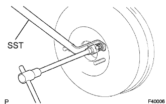
  1. If the clearance is out of the specified range, fix the push rod using SST and adjust the adjusting bolt protruding length.

    SST
    09737-00020  

    HINT:
    When adjusting the push rod, depress the brake pedal sufficiently so that the push rod sticks out.


2. INSTALL BRAKE MASTER CYLINDER
  1. Install a new O-ring onto the brake master cylinder.


    F050568
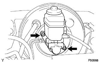
  1. Install the brake master cylinder with the 2 nuts onto the brake booster.
    Torque:
    12.5 N*m{ 127 kgf*cm , 9 ft.*lbf }


    F050567
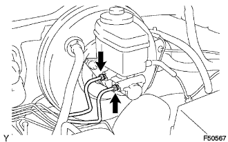
  1. Using SST, connect the 2 brake lines to the brake master cylinder.
    SST
    09023-00101  

    Torque:
    15 N*m{ 153 kgf*cm , 11 ft.*lbf }


    F050566
  1. for Manual Transmission:

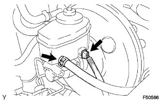
    1. Connect the clutch reservoir tube to the reservoir.

  1. Connect the brake fluid level warning switch connector to the brake master cylinder.


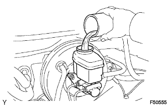
3. FILL RESERVOIR WITH BRAKE FLUID


F050555

Fluid:
SAE J1703 or FMVSS NO. 116 DOT3


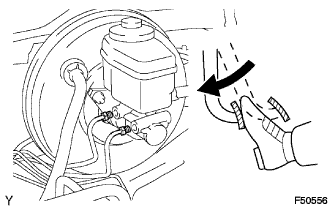
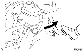
4. BLEED MASTER CYLINDER


F050556

HINT:
If the master cylinder has been disassembled or if the reservoir becomes empty, bleed the air from the master cylinder.

  1. Using SST, disconnect the brake lines from the master cylinder.

    SST
    09023-00101  

  1. Slowly depress the brake pedal and hold it there (step A).


    F050557
  1. Block the outer holes with your fingers, and release the brake pedal (step B).

  1. Repeat step A and B 3 or 4 times.


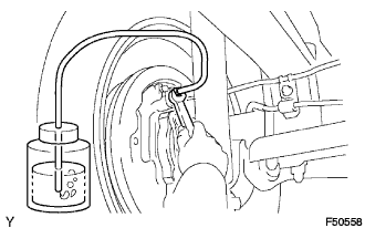
5. BLEED BRAKE LINE


F050558
  1. Connect the vinyl tube to the bleeder plug.

  1. Depress the brake pedal several times, then loosen the bleeder plug with the pedal held down (step C).

  1. At the point where the fluid stops coming out, tighten the bleeder plug, then release the brake pedal (step D).

  1. Repeat step C and D until all the air in the fluid has been bled out.

  1. Repeat the above procedure to bleed the air out of the brake line for each wheel.

    Torque:
    11 N*m{ 112 kgf*cm , 8 ft.*lbf }


6. CHECK FLUID LEVEL IN RESERVOIR
  1. Check the fluid level and add fluid if necessary.

    Fluid:
    SAE J1703 or FMVSS NO. 116 DOT3


7. CHECK FOR BRAKE FLUID LEAKAGE


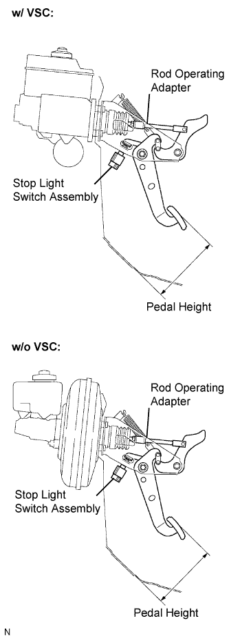
8. INSPECT BRAKE PEDAL HEIGHT


C114968E01
  1. Check the brake pedal height.

    Pedal height from dash panel:
    158.1 to 168.1 mm (6.224 to 6.618 in.)

    NOTICE:
    Do not adjust the pedal height. Doing so by changing the push rod length will structurally change the pedal ratio.

    If the pedal height is incorrect, adjust the rod operating adapter length.


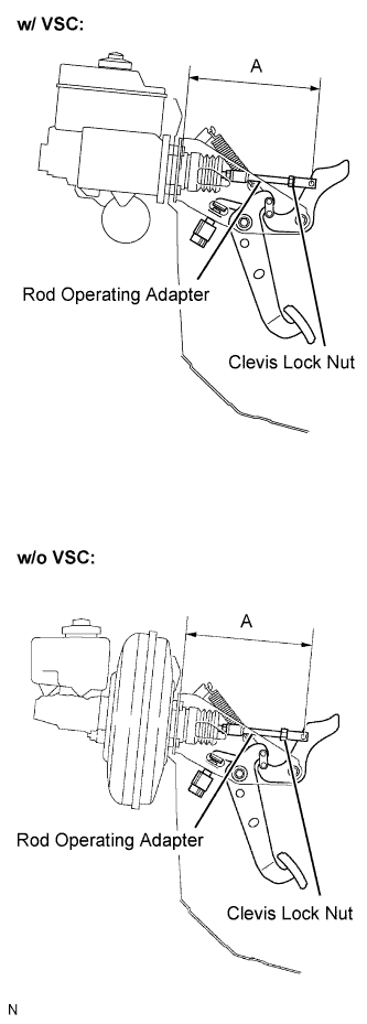
    C114969E01
  1. Adjust the rod operating adapter length.

    1. Remove the clip and clevis pin.

    2. Loosen the clevis lock nut.

    3. Adjust the rod operating adapter length by turning the pedal push rod clevis.

      Rod operating adapter length A:
      w/ VSC:
      214 to 224 mm (8.425 to 8.818 in.)
      w/o VSC:
      212 to 222 mm (8.346 to 8.740 in.)

    4. Tighten the clevis lock nut.

      Torque:
      25.5 N*m{ 260 kgf*cm , 19 ft.*lbf }

    5. Install the clip and clevis pin.

      1. If the pedal height is incorrect even when the rod operating adapter is adjusted, check that there is no damage in the brake pedal, brake pedal lever, brake pedal bracket or dash panel.
      2. Even if there is damage, there is no problem if the reserve distance is within the standard value.
      3. If necessary, replace the parts.


9. INSPECT PEDAL FREE PLAY


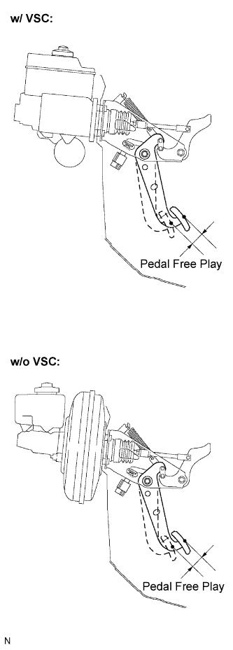
C114970E01
  1. Stop the engine and depress the brake pedal several times until there is no more vacuum left in the booster.

  1. Push in the pedal until the beginning of the resistance is felt. Measure the distance as shown.

    Pedal free play:
    1 to 6 mm (0.04 to 0.24 in.)


10. INSPECT PEDAL RESERVE DISTANCE


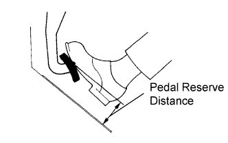
R000934E10
  1. Release the parking brake pedal.
    With the engine running, depress the pedal and measure the pedal reserve distance as shown.

    Pedal reserve distance from asphalt sheet at 490 N (50 kgf, 110.2 lbf):
    More than 55 mm (2.17 in.)

    If incorrect, troubleshoot the brake system.


11. CONNECT CABLE TO NEGATIVE BATTERY TERMINAL

Torque:
3.9 N*m{ 40 kgf*cm , 35 in.*lbf }

(Click here)