 |
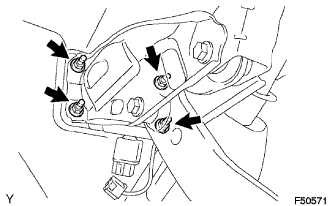
Install the brake booster assembly with the 4 nuts.
- Torque:
- 14.2 N*m{ 145 kgf*cm , 10 ft.*lbf }
BRAKE BOOSTER (w/o VSC) > INSTALLATION |
| 1. INSTALL BRAKE BOOSTER |
Install a new gasket onto the brake booster.
|
Install the brake booster assembly with the 4 nuts.
Connect the vacuum hose to the brake booster.
| 2. INSTALL MASTER CYLINDER PUSH ROD CLEVIS |
Apply lithium soap base glycol grease to the inner surface of the hole on the brake pedal lever.
Install the push rod clevis onto the brake pedal lever with the push rod pin and clip.
| 3. INSTALL BRAKE MASTER CYLINDER |
Install a new O-ring onto the brake master cylinder.
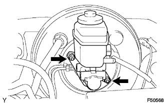 |
Install the brake master cylinder with the 2 nuts onto the brake booster.
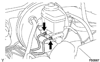 |
Using SST, connect the 2 brake lines to the brake master cylinder.
 |
for Manual Transmission:
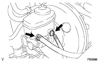
Connect the clutch reservoir tube to the reservoir.
Connect the brake fluid level warning switch connector to the brake master cylinder.
| 4. FILL RESERVOIR WITH BRAKE FLUID |
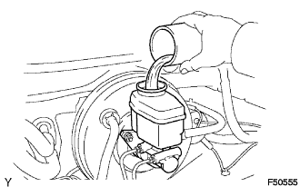 |
| 5. BLEED MASTER CYLINDER |
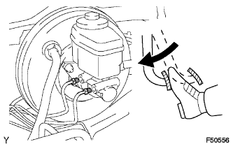 |
Using SST, disconnect the brake lines from the master cylinder.
Slowly depress the brake pedal and hold it there (step A).
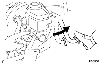 |
Block the outer holes with your fingers, and release the brake pedal (step B).
Repeat step A and B 3 or 4 times.
| 6. BLEED BRAKE LINE |
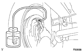 |
Connect the vinyl tube to the bleeder plug.
Depress the brake pedal several times, then loosen the bleeder plug with the pedal held down (step C).
At the point where the fluid stops coming out, tighten the bleeder plug, then release the brake pedal (step D).
Repeat step C and D until all the air in the fluid has been bled out.
Repeat the above procedure to bleed the air out of the brake line for each wheel.
| 7. CHECK FLUID LEVEL IN RESERVOIR |
Check the fluid level and add fluid if necessary.
| 8. CHECK FOR BRAKE FLUID LEAKAGE |
| 9. INSPECT BRAKE PEDAL HEIGHT |
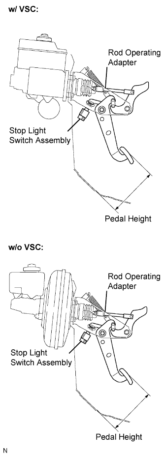 |
Check the brake pedal height.
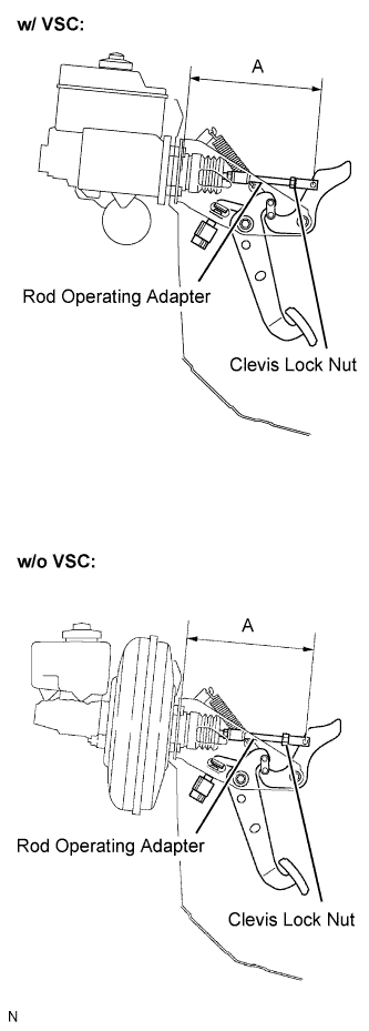 |
Adjust the rod operating adapter length.
Remove the clip and clevis pin.
Loosen the clevis lock nut.
Adjust the rod operating adapter length by turning the pedal push rod clevis.
Tighten the clevis lock nut.
Install the clip and clevis pin.
| 10. INSPECT PEDAL FREE PLAY |
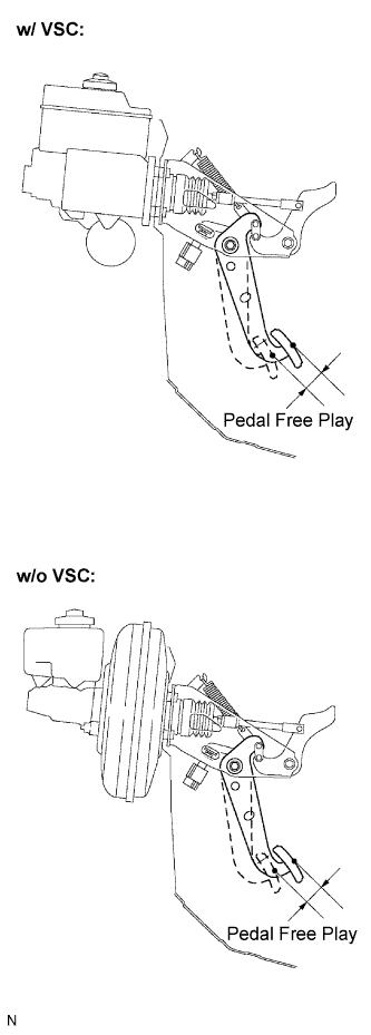 |
Stop the engine and depress the brake pedal several times until there is no more vacuum left in the booster.
Push in the pedal until the beginning of the resistance is felt. Measure the distance as shown.
| 11. INSPECT PEDAL RESERVE DISTANCE |
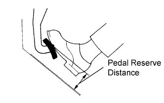 |
Release the parking brake pedal.
With the engine running, depress the pedal and measure the pedal reserve distance as shown.
| 12. INSTALL DRIVER SIDE JUNCTION BLOCK |
| 13. INSTALL INSTRUMENT PANEL FINISH PANEL LOWER NO. 1 |
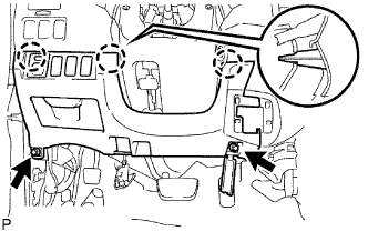 |
Connect the connectors.
Engage the 3 clips and install the lower NO. 1 instrument panel finish panel sub-assembly.
Install the 2 bolts <B>.
| 14. INSTALL INSTRUMENT PANEL UNDER TRAY (for Automatic Transmission) |
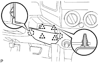 |
Engage the 4 clips and 2 claws, and install the instrument panel under tray.
| 15. INSTALL INSTRUMENT PANEL HOLE COVER (for Manual Transmission) |
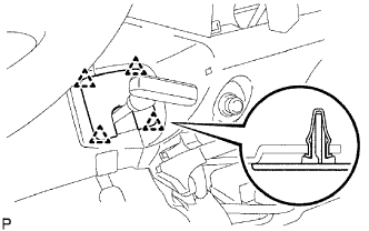 |
Engage the 4 clips and install the instrument panel hole cover.
| 16. INSTALL COWL SIDE TRIM BOARD (for Regular Cab) |
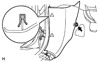 |
Engage the 2 clips and install the cowl side trim board.
Install the clip.
| 17. INSTALL COWL SIDE TRIM BOARD (for Access Cab) |
|
Engage the 2 clips and install the cowl side trim board.
Install the clip.
| 18. INSTALL COWL SIDE TRIM BOARD (for Double Cab) |
|
Engage the 2 clips and install the cowl side trim board.
Install the clip.
| 19. INSTALL FRONT DOOR SCUFF PLATE (for Regular Cab) |
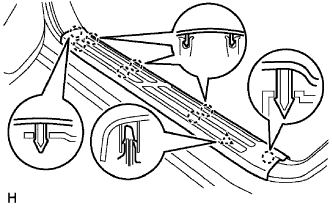 |
Engage the 8 claws and clip, and install the front door scuff plate.
| 20. INSTALL FRONT DOOR SCUFF PLATE (for Access Cab) |
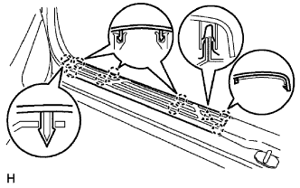 |
Engage the 9 claws and clip, and install the front door scuff plate.
| 21. INSTALL FRONT DOOR SCUFF PLATE (for Double Cab) |
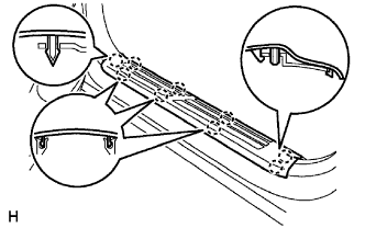 |
Engage the 9 claws and install the front door scuff plate.
| 22. INSTALL FRONT FLOOR FOOTREST |
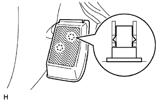 |
Engage the 2 clips and install the front floor footrest.
| 23. CONNECT CABLE TO NEGATIVE BATTERY TERMINAL |