FRONT DIFFERENTIAL CARRIER ASSEMBLY (for 4WD) > REMOVAL |
| 1. DISCONNECT CABLE FROM NEGATIVE BATTERY TERMINAL |
| 2. REMOVE FRONT WHEELS |
| 3. REMOVE NO.2 ENGINE UNDER COVER SUB-ASSEMBLY |
Remove the 4 bolts and No. 2 engine under cover sub-assembly.
| 4. REMOVE NO.1 ENGINE UNDER COVER SUB-ASSEMBLY |
Remove the 4 bolts and No. 1 engine under cover sub-assembly.
| 5. DRAIN DIFFERENTIAL OIL |
|
Stop the vehicle on a level place.
Remove the differential filler plug and gasket.
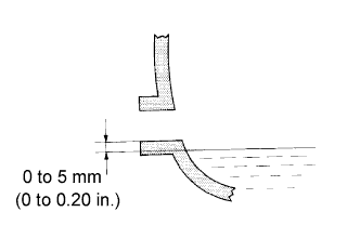
Check that the oil level is within 5mm (0 to 0.20 in.) of the bottom of the filler plug opening.
Check for oil leakage if the oil level is low.
Install the differential filler plug and a new gasket.
| 6. REMOVE FRONT PROPELLER SHAFT ASSEMBLY |
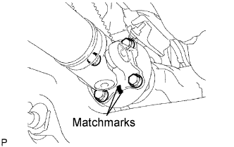 |
Place matchmarks on the propeller shaft flange and differential flange.
Remove the 4 nuts, 4 bolts, 4 washers and front propeller shaft.
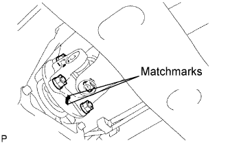 |
Place matchmarks on the propeller shaft flange and transfer flange.
Remove the 4 nuts, 4 washers and front propeller shaft.
| 7. REMOVE FRONT AXLE HUB LH NUT |
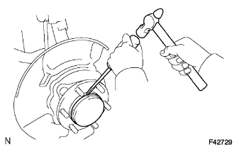 |
Using a screwdriver and a hammer, remove the front axle hub grease cap.
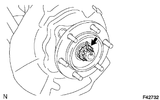 |
Remove the cotter pin and adjusting cap.
Remove the front axle hub nut.
| 8. REMOVE FRONT AXLE HUB RH NUT |
| 9. SEPARATE FRONT STABILIZER LINK ASSEMBLY LH |
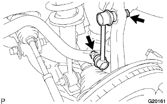 |
Remove the 2 nuts and front stabilizer link LH.
| 10. SEPARATE FRONT STABILIZER LINK ASSEMBLY RH |
| 11. SEPARATE FRONT SPEED SENSOR LH |
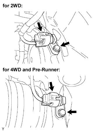 |
Disconnect the speed sensor connector.
Remove the bolt and front speed sensor.
| 12. SEPARATE FRONT SPEED SENSOR RH |
| 13. SEPARATE TIE ROD END SUB-ASSEMBLY LH |
Remove the cotter pin and nut.
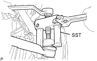 |
Using SST, separate the tie rod end from the steering knuckle arm.
| 14. SEPARATE TIE ROD END SUB-ASSEMBLY RH |
| 15. REMOVE FRONT SUSPENSION LOWER ARM LH |
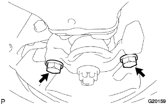 |
Remove the 2 bolts and separate the front lower ball joint attachment front from the steering knuckle.
| 16. REMOVE FRONT SUSPENSION LOWER ARM RH |
| 17. REMOVE FRONT DRIVE SHAFT ASSEMBLY LH |
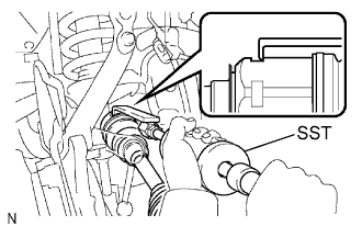 |
Using SST, remove the front drive shaft.
| 18. REMOVE FRONT DRIVE SHAFT ASSEMBLY RH |
| 19. REMOVE FRONT DIFFERENTIAL CARRIER ASSEMBLY |
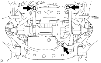 |
Remove the bolt and separate the front differential breather tube bracket.
Support the front differential with a jack.
Remove the front differential mount nut No. 1.
Remove the 2 front mounting bolts and 2 nuts.
Disconnect the actuator hose and connector.
Lower the jack and remove the front differential assembly.
Remove the 2 bolts and No. 3 front differential support.
Remove the 5 bolts and 2 front differential supports.