ENGINE UNIT > REPLACEMENT |
| 1. REMOVE TIMING CHAIN COVER OIL SEAL |
|
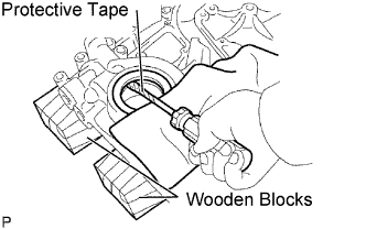
Using a screwdriver with its tip taped, pry out the oil seal.
| 2. INSTALL TIMING CHAIN COVER OIL SEAL |
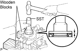 |
Place the timing chain cover on wooden blocks.
Using SST, tap in a new oil seal until its surface is flush with the timing gear case edge.
| 3. REMOVE ENGINE REAR OIL SEAL |
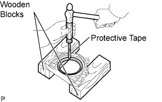 |
Place the oil seal retainer on wooden blocks.
Using a screwdriver with its tip taped and a hammer, tap out the oil seal.
| 4. INSTALL ENGINE REAR OIL SEAL |
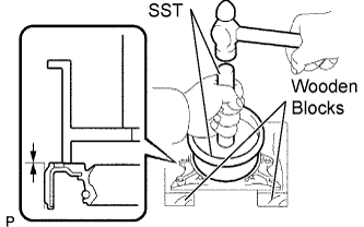 |
Place the oil seal retainer on wooden blocks.
Using SST, tap in a new oil seal until its surface is flush with the oil seal retainer edge.
| 5. REMOVE INTAKE VALVE GUIDE BUSH |
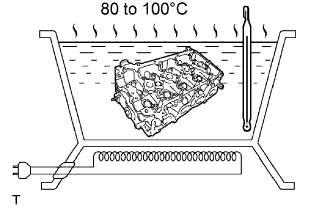 |
Heat the cylinder head to 80 to 100 °C(176 to 212°F).
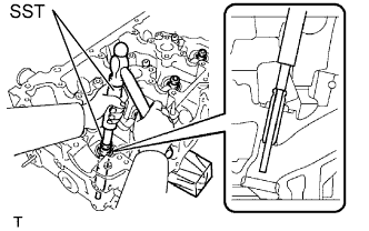 |
Place the cylinder head on wooden blocks.
Using SST and a hammer, tap out the guide bush.
| 6. INSTALL INTAKE VALVE GUIDE BUSH |
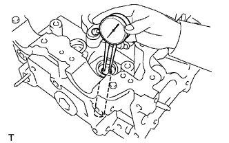 |
Using a caliper gauge, measure the bush bore diameter of the cylinder head.
Select a new guide bush (STD or O/S 0.05).
| Bush bore diameter | Bush size |
| 10.285 to 10.306 mm (0.4049 to 0.4057 in.) | Use STD |
| 10.335 to 10.356 mm (0.4069 to 0.4077 in.) | Use O/S 0.05 |
|
Heat the cylinder head to 80 to 100°C (176 to 212°F).
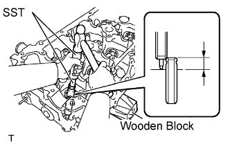 |
Place the cylinder head on wooden blocks.
Using SST, tap in a new valve guide bush to the specified protrusion height.
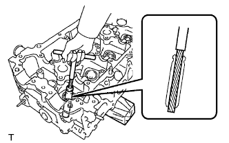 |
Using a sharp 5.5 mm reamer, ream the valve guide bush to obtain the standard specified clearance.
| 7. REMOVE EXHAUST VALVE GUIDE BUSH |
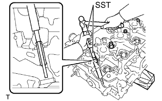 |
Heat the cylinder head to 80 to 100°C(176 to 212°F)
Place the cylinder head on wooden blocks.
Using SST and a hammer, tap out the guide bush.
| 8. INSTALL EXHAUST VALVE GUIDE BUSH |
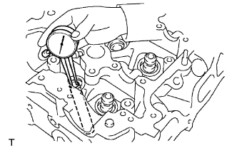 |
Using a caliper gauge, measure the bush bore diameter of the cylinder head.
Select a new guide bush (STD or O/S 0.05).
| Bush bore diameter | Bush size |
| 10.285 to 10.306 mm (0.4049 to 0.4057 in.) | Use STD |
| 10.335 to 10.356 mm (0.4069 to 0.4077 in.) | Use O/S 0.05 |
|
Heat the cylinder head to 80 to 100°C (176 to 212°F).
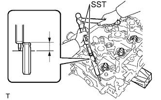 |
Place the cylinder head on wooden blocks.
Using SST, tap in a new valve guide bush to the specified protrusion height.
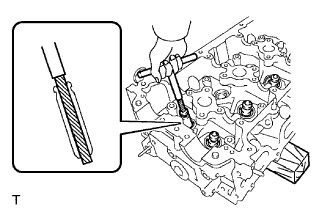 |
Using a sharp 5.5 mm reamer, ream the valve guide bushing to obtain the standard specified clearance.
| 9. REMOVE CONNECTING ROD SMALL END BUSH |
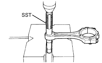 |
Using SST and a press, press out the bush.
| 10. INSTALL CONNECTING ROD SMALL END BUSH |
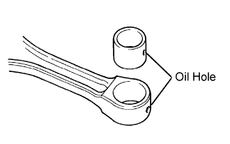 |
Align the oil holes of a new bush and the connecting rod.
|
Using SST and a press, press in the bush.
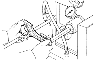 |
Using a pin hole grinder, hone the bush to obtain the standard specified clearance (see step 26.) between the bush and piston pin.
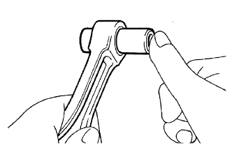 |
Check that the piston pin fits at normal room temperature.
Coat the piston pin with engine oil, and push it into the connecting rod with your thumb.