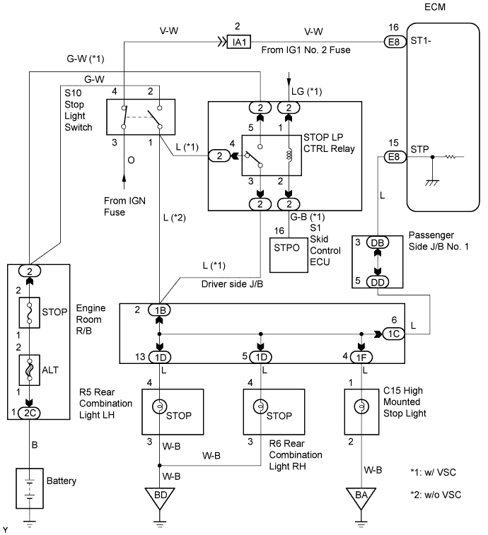
DTC P0724 Brake Switch "B" Circuit High |
| DTC No. | DTC Detection Conditions | Trouble Areas |
| P0724 | The stop light switch remains ON even when the vehicle repeats 5 cycles of STOP (less than 1.86 mph (3 km/h)) and GO (18.65 mph (30 km/h)or more) (2 trip detection logic) |
|
| Related DTCs | P0724: Stop light switch/Range check/Rationality |
| Required sensors/Components (Main) | Stop light switch |
| Required sensors/Components (Related) | Speed sensor |
| Frequency of Operation | Continuous |
| Duration | 5 times |
| MIL Operation | 2 driving cycles |
| Sequence of Operation | None |
| Monitor will run whenever following DTCs not present | None |
| GO: Vehicle speed | 18.65 mph (30 km/h) or more |
| STOP: Vehicle speed | Less than 1.86 mph (3 km/h) |
| Stop light switch status | Stuck ON |
| 1.READ VALUE OF INTELLIGENT TESTER (STOP LIGHT SW) |
Connect an intelligent tester to the DLC3.
Turn the ignition switch ON and turn the tester ON.
Select the following menu items: DIAGNOSIS / ENHANCED OBD II / DATA LIST / PRIMARY / STOP LIGHT SW.
Read the values displayed on the tester.
| Item | Measurement Item: Range (display) | Normal Condition |
| STOP LIGHT SW | Stop light switch status: ON or OFF |
|
|
| ||||
| NG | |
 |
| 2.INSPECT STOP LIGHT SWITCH ASSEMBLY |
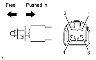 |
Remove the stop light switch assembly.
Check the resistance.
| Switch Positions | Tester Connections | Specified Conditions |
| Switch pin free | 1 - 2 | Below 1 Ω |
| Switch pin free | 3 - 4 | 10 kΩ or higher |
| Switch pin pushed in | 1 - 2 | 10 kΩ or higher |
| Switch pin pushed in | 3 - 4 | Below 1 Ω |
Reinstall the stop light switch assembly.
|
| ||||
| OK | |
|
| 3.CHECK HARNESS AND CONNECTOR (STOP LIGHT SWITCH - ECM) |
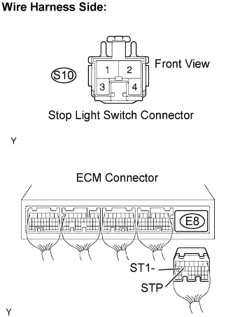 |
Disconnect the S10 stop light switch connector.
Disconnect the E8 ECM connector.
Check the resistance.
| Tester Connections | Specified Conditions |
| Stop light switch (S10-1) - STP (E8-15) | Below 1 Ω |
| Stop light switch (S10-4) - ST1- (E8-16) |
| Tester Connections | Specified Conditions |
| Stop light switch (S10-1) or STP (E8-15) - Body ground | 10 kΩ or higher |
| Stop light switch (S10-4) or ST1- (E8-16) - Body ground |
Reconnect the stop light switch connector.
Reconnect the ECM connector.
|
| ||||
| OK | ||
 | ||
| ||
