
POWER WINDOW CONTROL SYSTEM > TERMINALS OF ECU |
| POWER WINDOW REGULATOR MASTER SWITCH ASSEMBLY |
| *A | for Double Cab | *B | for Access Cab |
Disconnect the P9*1 or P18*2 power window regulator master switch assembly connector.
Measure the voltage and resistance according to the value(s) in the table below.
| Terminal No. | Wiring Color | Terminal Description | Condition | Specified Condition |
| P9-6 - P9-1 | R - W-B | Power supply | Ignition switch ON | 11 to 14 V |
| P9-1 - Body ground | W-B - Body ground | Ground | Always | Below 1 Ω |
| Terminal No. | Wiring Color | Terminal Description | Condition | Specified Condition |
| P18-15 - P18-7 | R - W-B | Power supply | Ignition switch ON | 11 to 14 V |
| P18-7 - Body ground | W-B - Body ground | Ground | Always | Below 1 Ω |
Reconnect the power window regulator master switch assembly connector.
Measure the voltage according to the value(s) in the table below.
| Terminal No. | Wiring Color | Terminal Description | Condition | Specified Condition |
| P9-3 - P9-1 | L - W-B | Power window motor UP operation | Ignition switch ON, driver door power window switch OFF → UP | 11 to 14 V → Below 1 V |
| P9-4 - P9-1 | L-B - W-B | Power window motor DOWN operation | Ignition switch ON, driver door power window switch OFF → DOWN (Manual operation) | 11 to 14 V → Below 1 V |
| Power window motor AUTO DOWN operation | Ignition switch ON, driver side door glass fully closed → driver side power window AUTO DOWN operation → driver side door glass fully opened | 11 to 14 V → Below 1 V → 11 to 14 V |
| Terminal No. | Wiring Color | Terminal Description | Condition | Specified Condition |
| P18-10 - P18-7 | L - W-B | Power window motor UP operation | Ignition switch ON, driver door power window switch OFF → UP (Manual operation) | 11 to 14 V → Below 1 V |
| P18-12 - P18-7 | L-B - W-B | Power window motor DOWN operation | Ignition switch ON, driver door power window switch OFF → DOWN (Manual operation) | 11 to 14 V → Below 1 V |
| Power window motor AUTO DOWN operation | Ignition switch ON, driver side door glass fully closed → driver side power window AUTO DOWN operation → driver side door glass fully opened | 11 to 14 V → Below 1 V → 11 to 14 V |
| CHECK DRIVER SIDE JUNCTION BLOCK ASSEMBLY (MULTIPLEX NETWORK BODY ECU) |
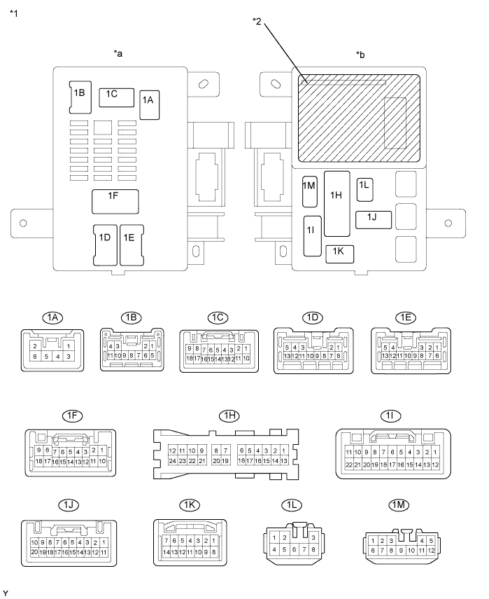
| *1 | Driver Side Junction Block Assembly | *2 | Multiplex Network Body ECU |
| *a | Vehicle Rear Side | *b | Vehicle Front Side |
Disconnect the 1A, 1C, 1F, 1H, 1I and 1K driver side junction block assembly connectors.
Measure the voltage and resistance according to the value(s) in the table below.
| Terminal No. (Symbol) | Wiring Color | Terminal Description | Condition | Specified Condition |
| 1C-16 (ECUB) - Body ground | R - Body ground | +B (ECUB) power supply | Always | 11 to 14 V |
| 1A-6 (ALTB) - Body ground | L - Body ground | +B (power system, generator system) power supply | Always | 11 to 14 V |
| 1H-18 (PWS) - Body ground | W-B - Body ground | PWR Relay ON signal | Ignition switch off | Below 1 V |
| Ignition switch ON | 11 to 14 V | |||
| 1K-10 (KSW) - Body ground | G-B - Body ground | Key unlock warning switch input | No key in ignition key cylinder | 10 kΩ or higher |
| Key inserted ignition key cylinder | Below 1 Ω | |||
| 1F-7 (DCTY) - Body ground | G-Y - Body ground | Driver side courtesy switch input | Driver side door CLOSED | 10 kΩ or higher |
| Driver side door OPEN | Below 1 Ω | |||
| 1I-8 (PCTY) - Body ground | R-B - Body ground | Passenger side courtesy switch input | Passenger side door CLOSED | 10 kΩ or higher |
| Passenger side door OPEN | Below 1 Ω | |||
| 1H-18 (GND) - Body ground | W-B - Body ground | Ground | Always | Below 1 Ω |
Reconnect the driver side junction block assembly connectors.
Measure the voltage according to the value(s) in the table below.
| Terminal No. (Symbol) | Wiring Color | Terminal Description | Condition | Specified Condition |
| 1K-10 (KSW) - Body ground | G-B - Body ground | Key unlock warning switch input | No key in ignition key cylinder | 11 to 14 V |
| Key inserted ignition key cylinder | Below 1 V |