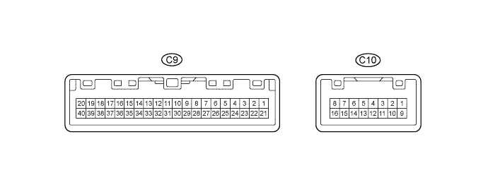
METER / GAUGE SYSTEM > TERMINALS OF ECU |
| COMBINATION METER ASSEMBLY |
Measure the voltage, resistance and check for pulse according to the value(s) in the table below.
| Terminals No. | Wiring Color | Terminal Description | Condition | Specified Condition |
| C9-1 - Body ground | R - Body ground | Battery | Always | 11 to 14 V |
| C9-2 - Body ground | W-B - Body ground | Ground | Always | Below 1 Ω |
| C9-4 - Body ground | Y-B - Body ground | Ground | Always | Below 1 Ω |
| C9-5 - Body ground | W - Body ground | Passenger side seat belt warning light signal (Output) | Ignition switch ON Front passenger seat occupied and its seat belt unfastened | 11 to 14 V → Below 1 V |
| Ignition switch ON Front passenger seat occupied and its seat belt fastened | 11 to 14 V | |||
| C9-6 - Body ground | R-Y - Body ground | Vehicle speed signal (Input) | Driving at approximately 20 km/h (12 mph) | Pulse generation (See waveform 1) |
| C9-7 - Body ground | W-L - Body ground | CAN communication signal | Ignition switch off | 200 Ω or higher |
| C9-8 - Body ground | L-Y - Body ground | CAN communication signal | Ignition switch off | 200 Ω or higher |
| C9-9 - Body ground | BE - Body ground | Fuel level signal | Ignition switch ON, fuel level FULL → EMPTY | Below 1 V → 4 to 7 V |
| C9-10 - Body ground | B-R - Body ground | Driver seat belt warning light signal | D-BELT warning light ON | Below 1 V |
| D-BELT warning light OFF | 11 to 14 V | |||
| C9-11 - Body ground | G-B - Body ground | Key switch condition signal | Key inserted | Below 1 V |
| Key removed | 11 to 14 V | |||
| C9-12 - Body ground | G-Y - Body ground | Driver side door open | Driver side door open | Below 1 V |
| Driver side door closed | 11 to 14 V | |||
| C9-16 - Body ground | GR - Body ground | Charge signal | Ignition switch ON | 11 to 14 V |
| Ignition switch off | Below 1 V | |||
| C9-17 - Body ground | BR - Body ground | MIL signal | MIL ON | Below 1 V |
| MIL OFF | 11 to 14 V | |||
| C9-18 - Body ground | G-W - Body ground | All door condition signal | Door open | Below 1 V |
| All doors closed | 11 to 14 V | |||
| C9-19 - Body ground | V-W - Body ground | Vehicle speed signal (4POUT) | Driving at approximately 20 km/h (12 mph) | Pulse generation (See waveform 1) |
| C9-20 - Body ground | W - Body ground | Illumination signal | Illumination switch OFF, rheostat maximum | 11 to 14 V |
| Illumination switch ON (wake up), rheostat maximum | Below 1 V | |||
| C9-21 - Body ground | V - Body ground | Ignition switch signal (ON) | Ignition switch off | Below 1 V |
| Ignition switch ON | 11 to 14 V | |||
| C9-23 - Body ground | L - Body ground | Tire pressure signal | Tire pressure indicator light ON | Below 3.2 V |
| Tire pressure indicator light OFF | 3.2 V or higher | |||
| C9-25 - Body ground | LG-B - Body ground | Oil pressure signal | Oil pressure warning light ON | Below 1 V |
| Oil pressure warning light OFF | 11 to 14 V | |||
| C9-26 - Body ground | B - Body ground | RSCA OFF indicator light input signal | Ignition switch ON RSCA OFF indicator light ON | Below 1 V |
| Ignition switch ON RSCA OFF indicator light OFF | 11 to 14 V | |||
| C9-27 - Body ground | SB - Body ground | Turn signal R | Ignition switch ON, turn signal RH indicator OFF | Below 1 V |
| Ignition switch ON, turn signal RH indicator ON | 11 to 14 V | |||
| C9-28 - Body ground | Y - Body ground | Turn signal L | Ignition switch ON, turn signal LH indicator OFF | Below 1 V |
| Ignition switch ON, turn signal LH indicator ON | 11 to 14 V | |||
| C9-29 - Body ground | G-W - Body ground | Illumination signal (output) | Illumination switch OFF, rheostat maximum | 11 to 14 V |
| Illumination switch ON (wake up), rheostat maximum | Below 1 V | |||
| C9-32*2 - Body ground | R-B - Body ground | HEAD light signal | HEAD indicator light ON | Below 1 V |
| HEAD indicator light OFF | 11 to 14 V | |||
| C9-40 - Body ground | G - Body ground | TAIL signal | TAIL indicator light ON | Below 1 V |
| TAIL indicator light OFF | 11 to 14 V | |||
| C10-1*3 - Body ground | G-B - Body ground | A/T shift position signal (P) | A/T P indicator OFF | Below 1 V |
| A/T P indicator ON | 11 to 14 V | |||
| C10-2*3 - Body ground | R - Body ground | A/T shift position signal (R) | A/T R indicator OFF | Below 1 V |
| A/T R indicator ON | 11 to 14 V | |||
| C10-2*1 - Body ground | R - Body ground | M/T shift position signal (R) | M/T shift warning buzzer OFF | Below 1 V |
| M/T shift warning buzzer ON | 11 to 14 V | |||
| C10-3*3 - Body ground | L-W - Body ground | A/T shift position signal (N) | A/T N indicator OFF | Below 1 V |
| A/T N indicator ON | 11 to 14 V | |||
| C10-4*3 - Body ground | W - Body ground | A/T shift position signal (D) | A/T D indicator OFF | Below 1 V |
| A/T D indicator ON | 11 to 14 V | |||
| C10-5*4 - Body ground | B - Body ground | A/T shift position signal (4) | A/T 4 indicator OFF | Below 1 V |
| A/T 4 indicator ON | 11 to 14 V | |||
| C10-5*5 - Body ground | Y - Body ground | A/T shift position signal (3) | A/T 3 indicator OFF | Below 1 V |
| A/T 3 indicator ON | 11 to 14 V | |||
| C10-6*4 - Body ground | Y - Body ground | A/T shift position signal (3) | A/T 3 indicator OFF | Below 1 V |
| A/T 3 indicator ON | 11 to 14 V | |||
| C10-6*5 - Body ground | R-Y - Body ground | A/T shift position signal (2) | A/T 2 indicator OFF | Below 1 V |
| A/T 2 indicator ON | 11 to 14 V | |||
| C10-7*4 - Body ground | V - Body ground | A/T shift position signal (2) | A/T 2 indicator OFF | Below 1 V |
| A/T 2 indicator ON | 11 to 14 V | |||
| C10-7*5 - Body ground | G-Y - Body ground | A/T shift position signal (L) | A/T L indicator OFF | Below 1 V |
| A/T L indicator ON | 11 to 14 V | |||
| C10-8*4 - Body ground | G-Y - Body ground | A/T shift position signal (L) | A/T L indicator OFF | Below 1 V |
| A/T L indicator ON | 11 to 14 V | |||
| C10-11*6 - Body ground | LG - Body ground | BRAKE signal | BRAKE warning light ON | Below 1 V |
| BRAKE warning light OFF | 11 to 14 V | |||
| C10-12 - Body ground | P - Body ground | Hi-Beam signal | Hi-Beam OFF | Below 1 V |
| Hi-Beam ON | 11 to 14 V | |||
| C10-14*7 - Body ground | L-Y - Body ground | RR DIFF LOCK signal | RR DIFF LOCK indicator light ON | Below 1 V |
| RR DIFF LOCK indicator light OFF | 11 to 14 V | |||
| C10-15*8 - Body ground | GR-B - Body ground | 4WD signal | 4WD indicator ON | Below 1 V |
| 4WD indicator OFF | 11 to 14 V | |||
| C10-16*8 - Body ground | BR-W - Body ground | 4LO TRAC signal | 4LO indicator light ON | Below 1 V |
| 4LO indicator light OFF | 11 to 14 V |
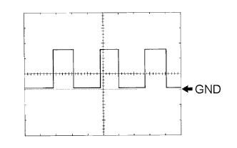 |
Waveform 1: Using an oscilloscope
| Item | Condition |
| Tester Connection | C9-6 - Body ground C9-19 - Body ground |
| Tool setting | 5 V/DIV., 20 ms/DIV |
| Vehicle condition | Driving at approximately 20 km/h (12 mph) |
| COMBINATION METER INNER CIRCUIT |
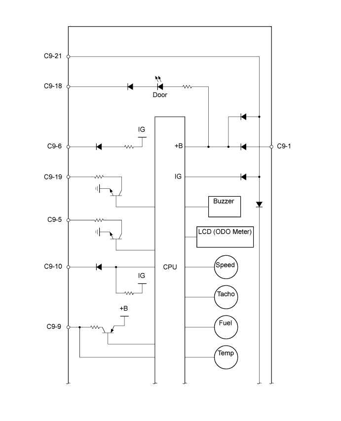
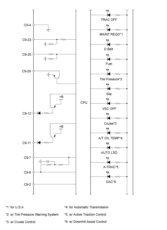
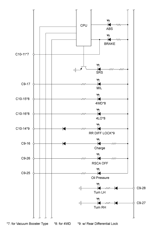
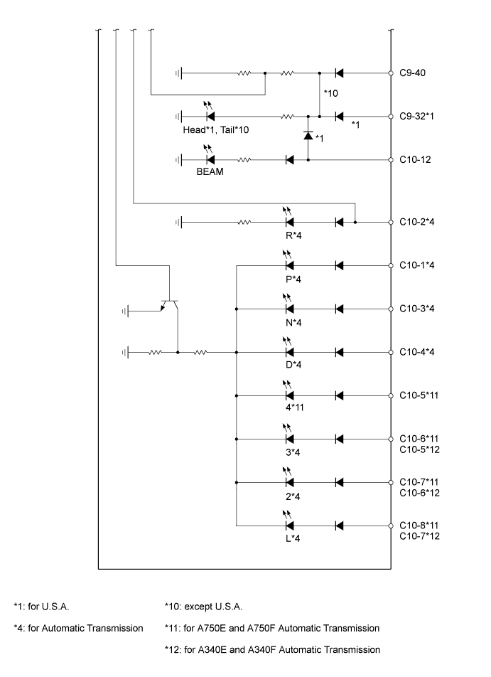
| Terminal No. | Wire Harness Side | |
| C9 | 1 | ECU-B fuse |
| 2 | Body ground | |
| 4 | Fuel sender gauge assembly | |
| 5 | Hazard warning signal switch assembly | |
| 6 | Brake actuator assembly | |
| 7 | CAN communication line (CANL) | |
| 8 | CAN communication line (CANH) | |
| 9 | Fuel sender gauge assembly | |
| 10 | Front seat inner belt assembly (Driver side) | |
| 11 | Unlock warning switch assembly | |
| 12 | Front door courtesy light switch (Driver side) | |
| 16 | Generator | |
| 17 | ECM | |
| 18 | Multiplex network body ECU | |
| 19 | 4P-OUT (Other parts) | |
| 20 | Light control rheostat | |
| 21 | GAUGE fuse | |
| 23 | Tire pressure warning ECU | |
| 25 | Engine oil pressure switch assembly | |
| 26 | Airbag sensor assembly | |
| 27 | Turn signal flasher assembly | |
| 28 | Turn signal flasher assembly | |
| 29 | No. 2 traction control switch (A-TRAC switch)*3 | |
| 32 | DIM relay*4 | |
| 40 | TAIL relay*5 | |
| C10 | 1 | Park/Neutral position switch assembly*2 |
| 2 | Park/Neutral position switch assembly*2 | |
| Back-up light switch assembly*1 | ||
| 3 | Park/Neutral position switch assembly*2 | |
| 4 | Shift lock control ECU*2 | |
| 5 | Shift lock control ECU*2 | |
| 6 | Park/Neutral position switch assembly*2 | |
| 7 | Shift lock control ECU*6 | |
| Park/Neutral position switch assembly*7 | ||
| 8 | Shift lock control ECU*6 | |
| 11 | Brake fluid level warning switch*8 | |
| 12 | DIM relay | |
| 14 | 4WD control ECU*9 | |
| 15 | 4WD control ECU*10 | |
| 16 | 4WD control ECU*10 | |