 |
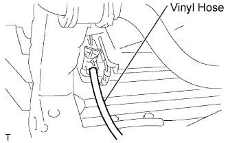
Install a vinyl hose onto the radiator side.
KNOCK SENSOR > REMOVAL |
| 1. DISCONNECT CABLE FROM NEGATIVE BATTERY TERMINAL |
| 2. REMOVE ENGINE UNDER COVER SUB-ASSEMBLY (for 4WD and Pre-Runner) |
| 3. DRAIN ENGINE COOLANT |
Remove the 4 bolts, then remove the engine under cover No. 1. (PRE RUNNER AND 4WD TYPE)
|
Install a vinyl hose onto the radiator side.
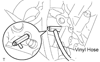 |
Install a vinyl hose onto the engine side.
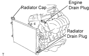 |
Loosen the engine drain plug.
Loosen the radiator drain plug.
Remove the radiator cap and drain coolant.
Drain the coolant from the reservoir tank.
| 4. REMOVE INTAKE AIR CONNECTOR |
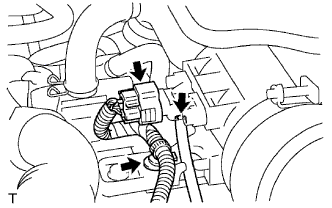 |
Disconnect the pressure sensor connector.
Disengage the wire harness clamp.
Disconnect the vacuum hose.
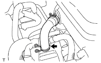 |
Disconnect the No. 2 ventilation hose.
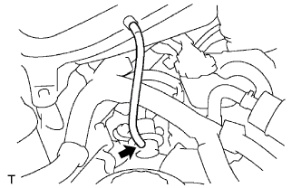 |
Disconnect the vacuum hose.
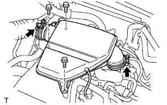 |
Loosen the 2 hose clamp bolts.
Remove the 3 bolts, then remove the intake air connector.
| 5. REMOVE THROTTLE WITH MOTOR BODY ASSEMBLY |
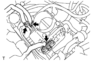 |
Disconnect the water by-pass hose.
Disconnect the No. 2 water by-pass hose.
Disconnect the throttle motor connector.
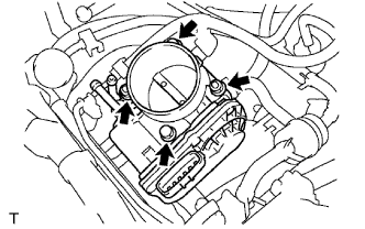 |
Remove the 2 bolts and 2 nuts, then remove the throttle with motor body.
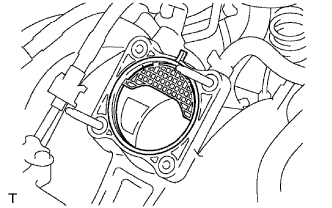 |
Remove the gasket from the intake manifold.
| 6. DISCONNECT FUEL HOSE |
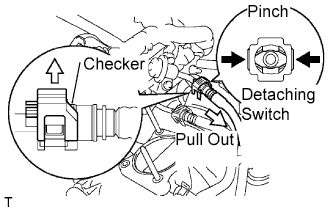 |
Pull the checker of the fuel hose upward.
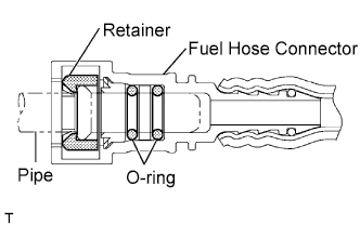
Pinch the detaching switch of the fuel hose connector and pull out the fuel hose.
 |
| 7. DISCONNECT NO. 2 FUEL HOSE |
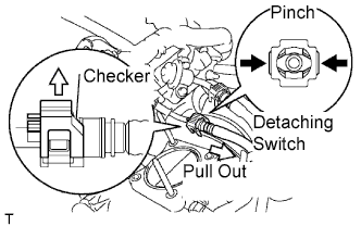 |
Pull the checker of the fuel hose upward.
Pinch the detaching switch of the fuel hose connector and pull out the fuel hose.
|
| 8. REMOVE INTAKE MANIFOLD |
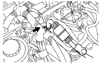 |
Disconnect the fuel vapor feed hose from the VSV.
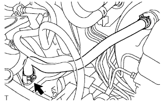 |
Disconnect the vacuum hose.
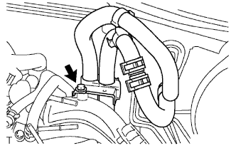 |
Remove the bolt, then remove the clamp bracket.
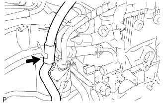 |
Disconnect the water by-pass hose No. 2.
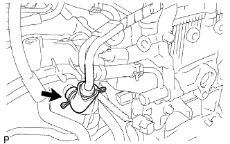 |
Disconnect the ventilation hose No. 3.
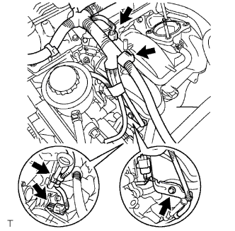 |
Disconnect the VSV connector.
Disengage the engine wire harness clamp.
Disconnect the compressor magnetic clutch connector. (w/ AIR CONDITIONING)
Disengage the wire harness clamp.
Remove the bolt and harness clamp bracket.
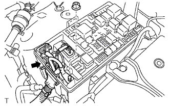 |
Disconnect the 3 connectors.
Remove the nut shown in the illustration.
Disconnect the engine wire harness from the relay block.
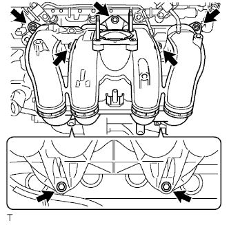 |
Remove the 5 bolts and 2 nuts, then remove the intake manifold.
| 9. REMOVE KNOCK CONTROL SENSOR |
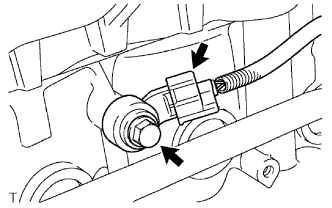 |
Disconnect the knock control sensor connector.
Remove the bolt, then remove the knock control sensor.