STEERING COLUMN ASSEMBLY > INSTALLATION |
| 1. INSTALL STEERING COLUMN ASSEMBLY |
|
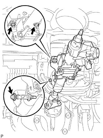
Install the steering column assembly with the 2 nuts and bolt.
Connect each of the connectors to the steering column assembly.
Connect the wire harness clamps to the steering column assembly.
| 2. INSTALL NO.2 STEERING INTERMEDIATE SHAFT |
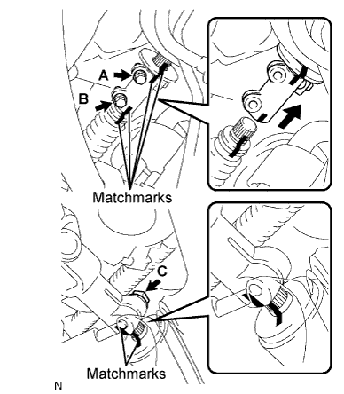 |
Align the matchmarks on the power steering gear and No. 2 steering intermediate shaft.
Install the No. 2 steering intermediate shaft onto the steering gear box with bolt C.
| 3. INSTALL STEERING SLIDING YOKE |
Align the matchmarks on the steering column and steering sliding yoke.
Install the steering sliding yoke onto the steering column assembly and slide it upward.
Align the matchmarks on the intermediate shaft sub-assembly No. 2 and steering sliding yoke.
Install the sliding yoke onto the intermediate shaft sub- assembly No. 2 with bolts A and B.
| 4. INSTALL NO.1 ENGINE UNDER COVER SUB-ASSEMBLY |
Install the No. 1 engine under cover sub-assembly with the 4 bolts.
| 5. INSTALL STEERING COLUMN HOLE COVER |
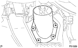 |
Install the steering column hole cover with the 4 clips.
| 6. INSTALL LOWER INSTRUMENT PANEL LH |
Install the lower instrument panel LH with the 3 bolts <B>.
| 7. INSTALL INSTRUMENT PANEL SUB-ASSEMBLY |
Connect the connectors.
Engage the 3 clips and install the lower NO. 1 instrument panel finish panel sub-assembly.
Install the 2 bolts <B>.
| 8. INSTALL INSTRUMENT PANEL HOLE COVER (for Lever Type Parking Brake) |
Engage the 4 clips and install the instrument panel hole cover.
| 9. INSTALL INSTRUMENT PANEL UNDER TRAY (for Pedal Type Parking Brake) |
Engage the 4 clips and 2 claws, and install the instrument panel under tray.
| 10. INSTALL COWL SIDE TRIM BOARD LH (for Regular Cab) |
Engage the 2 clips and install the cowl side trim board.
Install the clip.
| 11. INSTALL COWL SIDE TRIM BOARD LH (for Access Cab) |
Engage the 2 clips and install the cowl side trim board.
Install the clip.
| 12. INSTALL COWL SIDE TRIM BOARD LH (for Double Cab) |
Engage the 2 clips and install the cowl side trim board.
Install the clip.
| 13. INSTALL FRONT DOOR SCUFF PLATE LH (for Regular Cab) |
Engage the 8 claws and clip, and install the front door scuff plate.
| 14. INSTALL FRONT DOOR SCUFF PLATE LH (for Access Cab) |
Engage the 9 claws and clip, and install the front door scuff plate.
| 15. INSTALL FRONT DOOR SCUFF PLATE LH (for Double Cab) |
Engage the 9 claws and install the front door scuff plate.
| 16. INSTALL FRONT FLOOR FOOTREST |
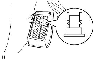 |
Engage the 2 clips and install the front floor footrest.
| 17. INSTALL WINDSHIELD WIPER SWITCH ASSEMBLY |
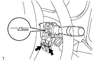 |
Engage the claw and install the windshield wiper switch assembly.
Connect the 2 connectors.
| 18. INSTALL SPIRAL CABLE SUB-ASSEMBLY |
Set the turn signal switch in neutral position.
Install the spiral cable sub-assembly with the 4 screws.
Connect the airbag connector and connector.
Install the steering column cover with the 3 screws.
| 19. INSTALL UPPER STEERING COLUMN COVER |
Engage the claw and then install the steering column cover upper.
| 20. INSTALL LOWER STEERING COLUMN COVER |
Engage the 2 claws.
Install the steering column cover lower with the 2 screws.
| 21. INSTALL STEERING WHEEL ASSEMBLY |
Align the matchmarks on the steering wheel assembly and steering main shaft assembly.
Install the steering wheel assembly set nut.
| 22. INSTALL STEERING PAD |
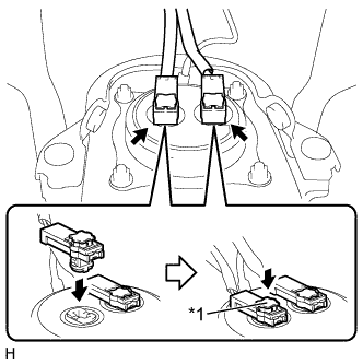 |
| *1 | Locking Button |
Check that the ignition switch is off.
Check that the cable is disconnected from the negative (-) battery terminal.
Connect the 2 airbag connectors.
Connect the horn terminal.
Install the steering pad.
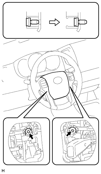 |
Using T30 "TORX" socket wrench, tighten the 2 bolts.
| 23. INSTALL NO.3 LOWER STEERING WHEEL COVER |
Engage the claw and install the No. 3 lower steering wheel cover onto the steering wheel assembly.
| 24. INSTALL NO.2 LOWER STEERING WHEEL COVER |
Engage the claw and install the No. 2 lower steering wheel cover onto the steering wheel assembly.
| 25. PLACE FRONT WHEELS FACING STRAIGHT AHEAD |
| 26. CONNECT CABLE TO NEGATIVE BATTERY TERMINAL |
| 27. INSPECT SRS WARNING LIGHT |