 |
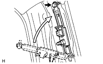
Insert the 2 claws of the front shoulder belt anchor adjuster into the hole in body and mount the bolt.
- Torque:
- 42 N*m{ 430 kgf*cm , 31 ft.*lbf }
FRONT SEAT OUTER BELT ASSEMBLY (for Regular Cab) > INSTALLATION |
| 1. INSTALL FRONT SHOULDER BELT ANCHOR ADJUSTER ASSEMBLY |
|
Insert the 2 claws of the front shoulder belt anchor adjuster into the hole in body and mount the bolt.
| 2. INSTALL FRONT SEAT OUTER BELT ASSEMBLY |
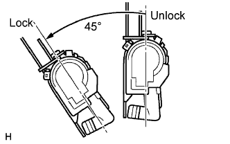 |
Check the amount of inclination required to lock the retractor.
Gently incline the retractor from its initial position. Check that belt does not lock when the retractor is inclined 15° or less in any directions. Also check that the belt locks when the inclination of the retractor is 45° or more.
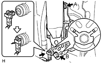 |
Hook the lower stay of the retractor onto the 2 body hooks.
Tighten bolt A, and then tighten bolt B.
Connect the pretensioner connector as shown in the illustration.
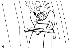 |
Install the shoulder anchor with the nut.
Check that the shoulder anchor rotates smoothly.
Check the ELR lock.
With the belt installed, check that the belt locks when it is pulled out quickly.
If operation is not as specified, replace the front seat outer belt.
| 3. INSTALL QUARTER INSIDE TRIM BOARD |
Engage the 2 clips and install the quarter trim board.
Tighten the 3 screws.
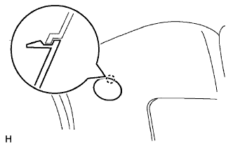 |
Engage the claw and close the cover.
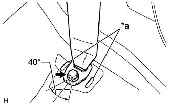 |
for LH Side and Separate Seat Type RH Side:
| *a | Convex |
Install the floor anchor of the front seat outer belt with the bolt.
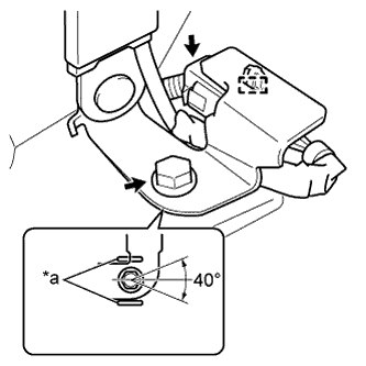 |
for Bench Seat Type RH Side:
| *a | Convex |
Install the wiring harness clamp.
Connect the belt tension sensor connector.
Install the floor anchor of the front seat outer belt with the bolt.
| 4. INSTALL QUARTER TRIM LOWER PANEL |
Engage the 2 claws and 3 clips, and install the quarter trim lower panel.
| 5. INSTALL BACK PANEL TRIM (for Separate Seat Type) |
Install the back panel trim with the 4 clips.
| 6. INSTALL JACK ASSEMBLY (for Separate Seat Type) |
| 7. INSTALL BACK PANEL UPPER GARNISH |
Engage the 4 claws and 5 clips, and install the back panel upper garnish.
| 8. INSTALL BACK PANEL TRIM COVER |
for Separate Seat Type and Bench Seat Type:
Engage the 6 claws and install the back panel trim cover.
for Bench Seat Type:
Engage the 6 claws and install the back panel trim cover.
| 9. INSTALL FRONT DOOR OPENING TRIM WEATHERSTRIP |
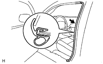 |
Install the front door opening trim weatherstrip.
| 10. INSTALL FRONT DOOR SCUFF PLATE |
Engage the 8 claws and clip, and install the front door scuff plate.
| 11. CONNECT CABLE TO NEGATIVE BATTERY TERMINAL |
| 12. INSPECT SRS WARNING LIGHT |