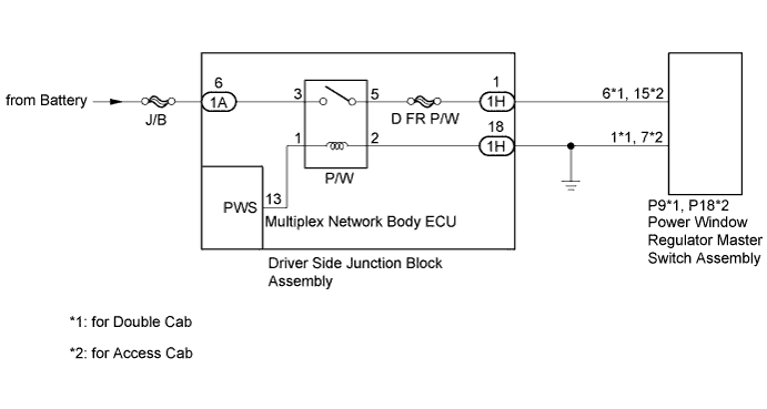
POWER WINDOW CONTROL SYSTEM > Power Windows do not Operate at All |
| 1.INSPECT P/W RELAY |
Remove the P/W relay from the driver side junction block assembly.
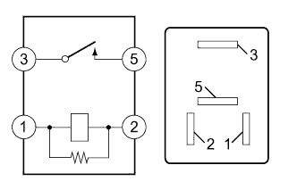 |
Measure the resistance according to the value(s) in the table below.
| Tester Connection | Condition | Specified Condition |
| 3 - 5 | Battery voltage not applied | 10 kΩ or higher |
| Battery voltage applied to terminal 1 and 2 | Below 1 Ω |
|
| ||||
| OK | |
 |
| 2.CHECK HARNESS AND CONNECTOR (DRIVER SIDE JUNCTION BLOCK - BATTERY AND BODY GROUND) |
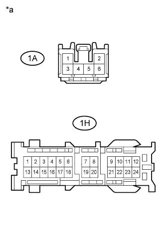 |
Disconnect the 1A and 1H driver side junction block assembly connectors.
Measure the voltage according to the value(s) in the table below.
| Tester Connection | Condition | Specified Condition |
| 1A-6 - Body ground | Always | 11 to 14 V |
Measure the resistance according to the value(s) in the table below.
| Tester Connection | Condition | Specified Condition |
| 1H-18 - Body ground | Always | Below 1 Ω |
| *a | Front view of wire harness connector (to Driver Side Junction Block Assembly) |
|
| ||||
| OK | |
|
| 3.CHECK HARNESS AND CONNECTOR (POWER WINDOW REGULATOR MASTER SWITCH ASSEMBLY - DRIVER SIDE JUNCTION BLOCK AND BODY GROUND) |
Disconnect the 1H driver side junction block assembly connector.
Disconnect the P9*1 or P18*2 power window regulator master switch assembly connector.
Measure the resistance according to the value(s) in the table below.
| Tester Connection | Condition | Specified Condition |
| P9-6 - 1H-1 | Always | Below 1 Ω |
| P9-6 - Body ground | Always | 10 kΩ or higher |
| P9-1 - Body ground | Always | Below 1 Ω |
| Tester Connection | Condition | Specified Condition |
| P18-15 - 1H-1 | Always | Below 1 Ω |
| P18-15 - Body ground | Always | 10 kΩ or higher |
| P18-7 - Body ground | Always | Below 1 Ω |
|
| ||||
| OK | |
|
| 4.CHECK DRIVER SIDE JUNCTION BLOCK ASSEMBLY |
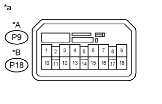 |
Disconnect the P9*1 or P18*2 power window regulator master switch assembly connector.
Measure the voltage according to the value(s) in the table below.
| Tester Connection | Switch Condition | Specified Condition |
| P9-6 - Body ground | Ignition switch ON | 11 to 14 V |
| Tester Connection | Switch Condition | Specified Condition |
| P18-15 - Body ground | Ignition switch ON | 11 to 14 V |
| *A | for Double Cab |
| *B | for Access Cab |
| *a | Front view of wire harness connector (to Power Window Regulator Master Switch Assembly) |
|
| ||||
| OK | ||
 | ||
| ||
