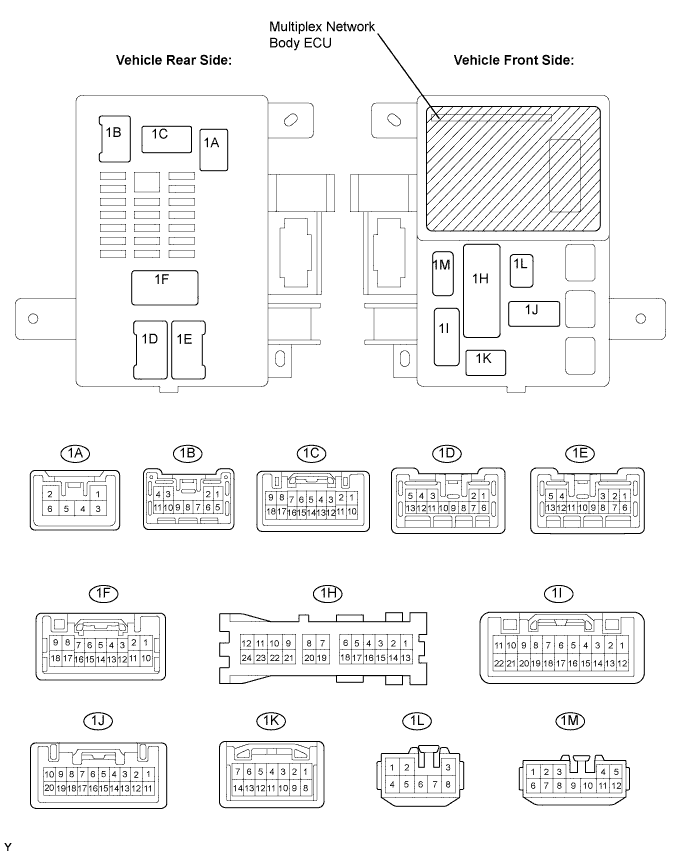
Symbols (Terminal No.)
| Wiring Color
| Terminal Description
| Condition
| Specified Condition
|
ALTB (1A-6) - Body ground
| L - Body ground
| +B (power system, generator system) power supply
| Always
| 10 to 14 V
|
ECUB (1C-16) - Body ground
| R - Body ground
| +B (ECUB) power supply
| Always
| 10 to 14 V
|
GND (1H-18) - Body ground
| W-B - Body ground
| Ground
| Always
| Below 1 Ω
|
KSW (1K-10) - Body ground
| G-B - Body ground
| Key unlock warning switch input
| No key in ignition key cylinder
| 10 kΩ or higher
|
Key inserted
| Below 1 Ω
|
DCTY (1F-7) - Body ground
| G-Y - Body ground
| Driver side courtesy switch input
| Driver side door closed
| 10 kΩ or higher
|
Driver side door open
| Below 1 Ω
|