 |
Inspect the servo motor operation.
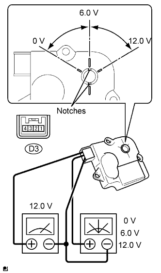
When 12V is applied between terminals 4 (IGN) and 1 (GND), and 0V is applied between terminals 2 (SIG) and 1 (GND), check that the line connecting the 2 notches moves to the 0V position.
If the result is not as specified, replace the mode control servo motor.When 12V is applied between terminals 4 (IGN) and 1 (GND), and 6V is applied between terminals 2 (SIG) and 1 (GND), check that the line connecting the 2 notches moves to the 6V position.
If the result is not as specified, replace the mode control servo motor.When 12V is applied between terminals 4 (IGN) and 1 (GND), and between terminals 2 (SIG) and 1 (GND), check that the line connecting the 2 notches moves to the 12V position.
If the result is not as specified, replace the mode control servo motor.