CONDENSER > INSTALLATION |
| 1. INSTALL COOLER CONDENSER ASSEMBLY |
|
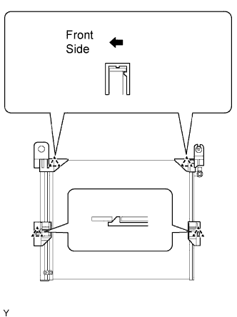
Engage the claw and install the condenser upper bracket LH.
Engage the claw and install the condenser upper bracket RH.
Engage the claw and install the condenser lower bracket LH.
Engage the claw and install the condenser lower bracket RH.
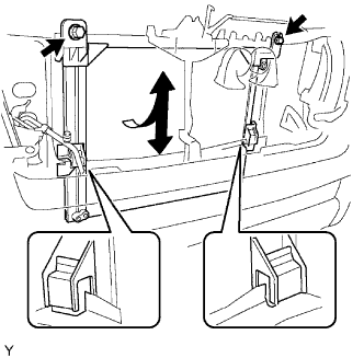 |
Lift the condenser up from the rear side of the vehicle, and install the condenser lower brackets onto the upper part of the radiator lower supports with the 2 bolts.
| 2. INSTALL AIR CONDITIONING TUBE ASSEMBLY |
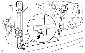 |
Remove the attached vinyl tape from the pipe and the connecting part of the cooler condenser assembly.
Apply sufficient compressor oil to a new seal washer and the fitting surface of the pipe joint.
Install the seal washer onto the air conditioning tube assembly.
Install the air conditioning tube assembly onto the cooler condenser assembly with the bolt.
| 3. INSTALL DISCHARGE HOSE SUB-ASSEMBLY |
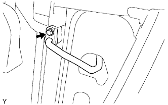 |
Remove the attached vinyl tape from the hose and the connecting part of the cooler condenser assembly.
Apply sufficient compressor oil to a new seal washer and the fitting surface of the hose joint.
Install the seal washer onto the discharge hose sub-assembly.
Install the discharge hose sub-assembly onto the cooler condenser assembly with the bolt.
| 4. INSTALL RADIATOR ASSEMBLY (for 2TR-FE) |
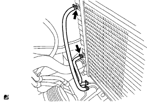 |
Install the radiator with the 4 bolts.
Connect the oil cooler inlet and outlet hoses. (for Automatic Transmission)
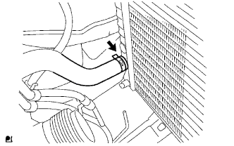 |
Connect the radiator hose NO. 2.
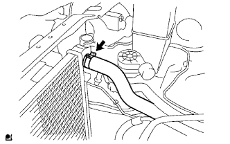 |
Connect the radiator hose inlet.
| 5. INSTALL RADIATOR ASSEMBLY (for 1GR-FE) |
Install the radiator with the 4 bolts.
Connect the 2 oil cooler hoses (with automatic transmission).
| 6. INSTALL FAN SHROUD (for 2TR-FE) |
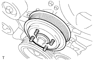 |
Install the fan pulley.
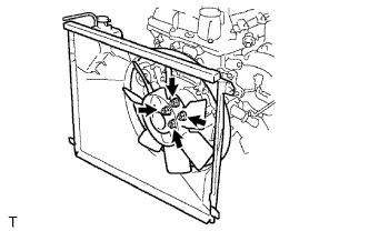 |
Install the fan shroud and fan with fluid coupling together.
Provisionally install the fan with fluid coupling with the 4 nuts.
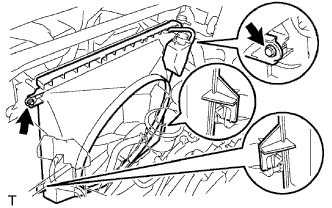 |
Install the 2 bolts shown in the illustration.
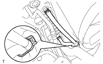 |
Connect the oil cooler inlet and outlet hoses to the fan shroud. (for Automatic Transmission)
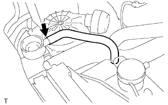 |
Connect the radiator reserve tank hose to the radiator.
Install the fan generator V belt.
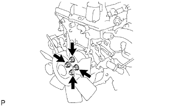 |
Tighten the 4 nuts shown in the illustration.
| 7. INSTALL FAN SHROUD (for 1GR-FE) |
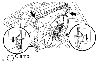 |
Provisionally install the fan shroud together with the fan pulley.
Install the fan and generator V belt .
Install the fan pulley with the 4 nuts.
Install the fan shroud with the 2 bolts.
Install the 2 cooler hoses into the clamp (with automatic transmission).
Connect the hose to the radiator reserve tank.
| 8. INSTALL RADIATOR SUPPORT TO FRAME SEAL LH (for 2TR-FE) |
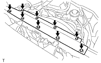 |
Install the radiator support frame seal LH with the 9 clips.
| 9. INSTALL RADIATOR SUPPORT TO FRAME SEAL LH (for 1GR-FE) |
| 10. INSTALL RADIATOR GRILLE |
Engage the 8 guides and install the radiator grille.
Install the 2 clips.
Tighten the 2 screws.
| 11. CONNECT CABLE TO NEGATIVE BATTERY TERMINAL |
| 12. ADD ENGINE COOLANT (for 2TR-FE) |
Tighten the engine drain plug.
Tighten the radiator drain plug.
Disconnect the 2 vinyl hoses.
Slowly fill the system with engine coolant.
Check the coolant level inside the radiator by squeezing the inlet and outlet radiator hoses several times by hand. If the coolant level goes down, add coolant.
Install the radiator cap securely.
Slowly pour coolant into the radiator reservoir until it reaches the FULL line.
Warm up the engine until the cooling fan operates.
| Item | Condition |
| Fan speed | Any setting except OFF |
| Temperature | Toward warm |
| Air condition switch | OFF |
Squeeze the inlet and outlet radiator hoses several times by hand while warning up the engine.
Stop the engine and wait until the coolant cools down.
Remove the radiator cap and check the coolant level inside the radiator.
If the coolant level is below the full level, perform the steps from (d) through (k) and repeat the operation until the coolant level remains at the full level.
Check the coolant level inside the radiator reservoir tank again. If it is below the full level, add coolant.
Install the engine under cover No. 1 with the 4 bolts. (PRE RUNNER AND 4WD TYPE)
| 13. ADD ENGINE COOLANT (for 1GR-FE) |
Pour coolant into the radiator until it overflows.
| Transmission | Capacity |
| Manual Transmission | 9.7 liters (10.3 Us qts, 8.5 Imp. qts) |
| Automatic Transmission | 9.8 liters (10.4 Us qts, 8.6 Imp. qts) |
Check the coolant level inside the radiator by squeezing the inlet and outlet radiator hoses several times by hand. If the coolant level goes down, add coolant.
Install the radiator cap securely.
Slowly pour coolant into the radiator reservoir until it reaches the FULL line.
Warm up the engine until the cooling fan operates.
Set the air conditioning as follows while warming up the engine.
| Item | Condition |
| Fan Speed | Any setting except OFF |
| Temperature | Toward WARM |
| Air Conditioning Switch | OFF |
Maintain the engine speed at 2,000 to 2,500 rpm and warm up the engine until the cooling fan operates.
Squeeze the inlet and outlet radiator hoses several times by hand while warming up the engine.
Stop the engine and wait until the coolant cools down.
Remove the radiator cap and check the coolant level inside the radiator.
If the coolant level is below the full level, perform the steps from (a) through (h) and repeat the operation until the coolant level remains at the full level.
Check the coolant level inside the radiator reservoir tank again. If it is below the full level, add coolant.
| 14. CHECK FOR ENGINE COOLANT LEAK (for 2TR-FE) |
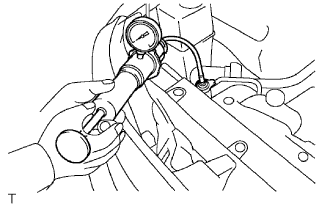 |
Fill the radiator with coolant and attach a radiator cap tester.
Warm up the engine.
Pump it up to 118 kPa (1.2 kgf/cm2, 17.1 psi) and check that the pressure does not drop.
| 15. CHECK FOR ENGINE COOLANT LEAK (for 1GR-FE) |
Fill the radiator with coolant and attach a radiator cap tester.
Pump it to 118 kPa (1.2 kgf/cm2 17.1 psi), then check for leakage.
| 16. CHARGE REFRIGERANT |
Perform vacuum purging using a vacuum pump.
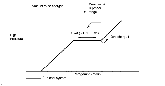
Charge refrigerant HFC-134a (R134a).
| 17. WARM UP ENGINE |
| 18. CHECK FOR REFRIGERANT LEAK |
After recharging the refrigerant gas, check for refrigerant gas leakage using a halogen leak detector.
Perform the operation under these conditions:
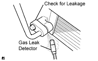 |
Using a gas leak detector, check the refrigerant line for leakage.
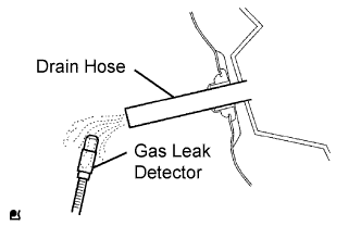 |
Bring the gas leak detector close to the drain hose with the detector power off.
If a gas leak is not detected from the drain hose, remove the blower motor control from the cooling unit. Insert the gas leak detector sensor into the unit and perform the test.
Disconnect the pressure switch connector and leave it for approximately 20 minutes. Bring the gas leak detector close to the pressure switch and perform the test.